Continue to Site

Welcome to EDAboard.com

Welcome to our site! EDAboard.com is an international Electronics Discussion Forum focused on EDA software, circuits, schematics, books, theory, papers, asic, pld, 8051, DSP, Network, RF, Analog Design, PCB, Service Manuals... and a whole lot more! To participate you need to register. Registration is free. Click here to register now.

[SOLVED] Solar charger Mosfet Connection

Status
Not open for further replies.

ismu

Full Member level 2
Full Member level 2
Joined
May 12, 2009
Messages
145
Helped
1
Reputation
2
Reaction score
1
Trophy points
1,298
Location
nil
Visit site
Activity points
2,340
Please check one of solar chager mosfet configration, here lower mosfet connection is ok , but upper is not propper i think (Drain < Sourse even it is a N- channel) . But it is working fine as per the schematic graph [in and out section]. Then How ? I want to explanation about upper mosfet how behave in this circuit? and what the benifit for this connection?
 

Attachments

  • Solar.pdf
    11.7 KB · Views: 232

I can't see the point on this circuit operating as a solar charger. However it may work as kind of low efficiency PWM voltage regulator depending on what load you connect at the output...
When Q2(G) signal is 12V, Q1 is OFF since Vgs = 0 and Q2 is ON. The current flows from R1 through Q1 intrinsic diode and Q2 (ON), therefore ouptut voltage is 0.
When Q2(G) signal is 0 V, Q2 is off and Q1 is off too because VGS = -12V... Therefore the output voltage is 12 V (considering you have no load).
The upper switch is useless in this application.
 
Here Solar pannel > battery then Gate ==12V
Now check is ther any use of upper MOSFET?
 

Attachments

  • Solar (1).pdf
    33.6 KB · Views: 193

There is no point in using Two Fets as you said, One is sufficient if the drain source voltage to the FET is within its limit
 
  • Like
Reactions: ismu

    ismu

    Points: 2
    Helpful Answer Positive Rating
I think its used for to prevent battrey volt return back to solar pannel .right ?
 

No solar panels are protected by giving output from it through a Diode
 
  • Like
Reactions: ismu

    ismu

    Points: 2
    Helpful Answer Positive Rating
When night what will happen ? battery will dischrge through Solar pannel ,Right?
 

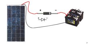
The diode is placed at the solar panel output to prevent the battery discharging through the solar panel at night or during the day when light level is okay and panel output voltage is less than battery voltage.
 
When night what will happen ? battery will dischrge through Solar pannel ,Right?
see the diagram diode will prevent any discharge at any time
4246261600_1359356358.jpg
 
  • Like
Reactions: ismu

    ismu

    Points: 2
    Helpful Answer Positive Rating
Please check one of solar chager mosfet configration, here lower mosfet connection is ok , but upper is not propper i think (Drain < Sourse even it is a N- channel) . But it is working fine as per the schematic graph [in and out section]. Then How ? I want to explanation about upper mosfet how behave in this circuit? and what the benifit for this connection?

The upper MOSFET is used not as a MOSFET, but actually as a diode (the MOSFET body diode is utilized) to prevent the battery discharging into the panel. Instead of a MOSFET, however, a diode should be used here, preferably a schottky diode, because the MOSFET body diode has a high forward voltage rating and so contributes to high voltage loss in the path.

Hope this helps.
Tahmid.
 
  • Like
Reactions: ismu

    ismu

    Points: 2
    Helpful Answer Positive Rating
Status
Not open for further replies.

Similar threads

Part and Inventory Search

Welcome to EDABoard.com

Sponsor

Back
Top