Continue to Site

Welcome to EDAboard.com

Welcome to our site! EDAboard.com is an international Electronics Discussion Forum focused on EDA software, circuits, schematics, books, theory, papers, asic, pld, 8051, DSP, Network, RF, Analog Design, PCB, Service Manuals... and a whole lot more! To participate you need to register. Registration is free. Click here to register now.

SMPS: use or not to use high freq. coef. multiplier for cap?

Status
Not open for further replies.

techieguy

Newbie level 2
Newbie level 2
Joined
Oct 2, 2013
Messages
2
Helped
0
Reputation
0
Reaction score
0
Trophy points
1
Visit site
Activity points
13
Hello guys,

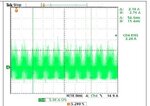
I'm looking for some help a couple days. I have the waveform attached, this is the ripple current (ac current) through a electrolytic cap. This cap in located on the output of a power factor correction circuit at the input stage (after the full wave rectifier bridge). There is a component frequency of 120Hz and switching noise of the PWM. The question is when choosing the cap, do I have to use frequency multiplier different that 1 to calculate the maximum ripple current?

Thank you for helping me.

Techie.
pic.jpg
 

Ripple current rating is probably mostly about not overheating the cap, due to equivalent series resistance (ESR) and the associated i-squared x R losses in the cap.

So since the ESR varies with frequency, you would probably want to determine what the ESR would be for each of the two (or more) dominant frequencies in your scope trace, and do an FFT to get the average or RMS current at each frequency, and make sure that the sum of the I-squared x ESR(f) for those two f (frequency) components will not generate too much temp rise (i.e. too many Watts). [Or, in general, you could integrate i²(f) x ESR(f), over frequency, to get the total RMS watts that would be dissipated in the cap.]

You can use the cap's rated ripple current frequency (and the ESR spec given for that frequency), and its maximum ripple current rating given for that frequency, to determine the TOTAL allowed maximum I-squared x ESR loss (i.e. the allowed maximum Watts the cap can dissipate).

If they only provide DF (dissipation factor) or tan(delta), you can calculate ESR from that, for the frequency specified: tan [delta] = ESR/Xc = ESR/(2[pi]fC). Solve for ESR.

The CDE (Cornell Dubilier) website has a Java applet that automatically produces a frequency and temperature dependent spice model for any of their electrolytic caps. And the models work well in time-domain simulations, as well as in frequency domain. That Java applet also provides a plot in your browser that shows the ESR vs frequency (and temperature), for any of their electrolytic caps. They also have some good appnotes, on their website.

(If we assume that CDE's caps are not too "special", and we find one that matches one ESR(f) data point for our actual cap, and has same value and voltage rating, then maybe we could assume that the ESR vs frequency that their Java applet gives will be applicable to our actual cap, roughly. Or, contact your cap's manufacturer, or, measure its ESR at the frequencies of interest.)
 
Last edited:

Thanks buddy for the valuable info.

Techie.


Ripple current rating is probably mostly about not overheating the cap, due to equivalent series resistance (ESR) and the associated i-squared x R losses in the cap.

So since the ESR varies with frequency, you would probably want to determine what the ESR would be for each of the two (or more) dominant frequencies in your scope trace, and do an FFT to get the average or RMS current at each frequency, and make sure that the sum of the I-squared x ESR(f) for those two f (frequency) components will not generate too much temp rise (i.e. too many Watts). [Or, in general, you could integrate i²(f) x ESR(f), over frequency, to get the total RMS watts that would be dissipated in the cap.]

You can use the cap's rated ripple current frequency (and the ESR spec given for that frequency), and its maximum ripple current rating given for that frequency, to determine the TOTAL allowed maximum I-squared x ESR loss (i.e. the allowed maximum Watts the cap can dissipate).

If they only provide DF (dissipation factor) or tan(delta), you can calculate ESR from that, for the frequency specified: tan [delta] = ESR/Xc = ESR/(2[pi]fC). Solve for ESR.

The CDE (Cornell Dubilier) website has a Java applet that automatically produces a frequency and temperature dependent spice model for any of their electrolytic caps. And the models work well in time-domain simulations, as well as in frequency domain. That Java applet also provides a plot in your browser that shows the ESR vs frequency (and temperature), for any of their electrolytic caps. They also have some good appnotes, on their website.

(If we assume that CDE's caps are not too "special", and we find one that matches one ESR(f) data point for our actual cap, and has same value and voltage rating, then maybe we could assume that the ESR vs frequency that their Java applet gives will be applicable to our actual cap, roughly. Or, contact your cap's manufacturer, or, measure its ESR at the frequencies of interest.)
 

Status
Not open for further replies.

Similar threads

Part and Inventory Search

Welcome to EDABoard.com

Sponsor

Back
Top