Continue to Site

Welcome to EDAboard.com

Welcome to our site! EDAboard.com is an international Electronics Discussion Forum focused on EDA software, circuits, schematics, books, theory, papers, asic, pld, 8051, DSP, Network, RF, Analog Design, PCB, Service Manuals... and a whole lot more! To participate you need to register. Registration is free. Click here to register now.

smps low pass filter diagram & values selection of inductor and capacitor

Status
Not open for further replies.

aqildad

Member level 2
Member level 2
Joined
Jun 8, 2014
Messages
46
Helped
1
Reputation
2
Reaction score
1
Trophy points
8
Visit site
Activity points
269
i am going to make pure sinewave smps inverter of below specification
1-load 800w
2-oscillator frequency is approx is 50khz
3-boost volt 315v dc
4-out put pure sine wave through h-bridge 220v ac at 50hz

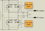
My problem is at Filter side below is my filter circuit and my questions

Copy of question.GIF

1-is filter circuit correct ?? if yes then what are the inductor and capacitor values ??
2-if the circuit is incorrect then what is the correct circuit ??? and what will be the exact values of capacitor and inductor ??
3-which side of the out put bridge is phase and neutral ? because input neutral will sink with out put neutral ???
 
Last edited:

i am going to make pure sinewave smps inverter of below specification
1-load 800w
2-oscillator frequency is approx is 50khz
3-boost volt 315v dc
4-out put pure sine wave through h-bridge 220v ac at 50hz

My problem is at Filter side below is my filter circuit and my questions

copy-question.gif

1-is filter circuit correct ?? if yes then what are the inductor and capacitor values ??
2-if the circuit is incorrect then what is the correct circuit ??? and what will be the exact values of capacitor and inductor ??
3-which side of the out put bridge is phase and neutral ? because input neutral will sink with out put neutral ???

Hi aqildad

Of course your filter and location of your load is incorrect . use just an LC ( LPF ) filter ( 2nd order ) . and put the load across the capacitor . to be more clear . use a series LC network and put your load across the capacitor . it will handle your aim as well . but be aware of mismatching ! such a filter deals with an out put impedance which if you don't consider it in your design it will mess everything up . i.e : feedback is also needed .

Best Wishes
Goldsmith
 

Hi,

Pwm frequency is 50kHz?
On first sight i'd decide the filter frequency at sqrt(50Hz x 50kHz) = about 3kHz.
The two inductivities you can calculate as one. So you get a second order low pass.
Your load is 800W at 220V. This means about 60 Ohms.
If it is ok for the filter to loose 5% of voltage, then you need a filter (inductor) impedance of 30% of the load impedance.
This gives an inductor impedance of 60 Ohms x 30% = 18 Ohms.
Now you can calculate the inductivity. Divide this value by two for each single inductivity.

Calculate the total inductive impedance at 3kHz. With this value calculate the capacity.

Estimation of remainig ripple voltage:
(150khz/3kHz)^2 = 2500 (ripple attenuation)
With about 300 V pwm ripple this means about 0.12V ripple at the load.
... this is a dirty calculation, but gives an order of magnitude....

Mind: at 3kHz you have resonance. Consider to damp this resonance if needed.

I recommend to use a RC combination in parallel with the load to avoide ringing in case the load is disconnected.
Also i reccomend to add EMI/EMC filter capacitor from each load connetion to Gnd/case.

If my estimations are right then this gives a very good filter,
One can shift the cutoff frequency higher, to get a smaller inductivity and capacity for smallercand cheaper parts, but one looses ripple attenuation...

Hope this helps
Klaus
 
this circuit is from tahmid blog in high dc conversion . circuit 50kHz.GIF

my question is why inductor and capacitor is connected here ?? if it is a low pas filter what is its calculation ??? what should be the ampere of inductor ??
 

I don't believe that anybody would operate a DC/DC converter at 50 Hz to supply a DC/AC H-bridge. In this case, the transformer could source 50 Hz AC directly.

Apart from this point, yes it looks like a low-pass. And the inductor rating would be 800W/315V, I suppose.
 

Referring to Post #4 schematic LPF 50KHz DC-DC converter

I use a similar rule of thumb as Klaus except decide how much ripple is acceptable at the source frequency and then determine the cost and size of the L & C parts based on the DC & AC current respectively.

A quick look at 3A chokes rated for 3A and 5A saturation gives values of 1 to 22uH in economical prices in SMT. 10uH@ 100kHz is 6.3 Ohms thus to get 1% ripple or 40 dB attenuation the impedance of the cap must be <1% of ZL or 0.06 Ohms @ 100KHz.

{Edit 0.6 to 0.06 Ohm and 2.7 to 27uF)

This equates to >27uF
For low self heating from ESR must be much lower based on ripple current I^2*ESR < ?? W depending on size of chip or can. General PUrpose Caps might be rated in Ripple current whereas low ESR caps are rated in milliohms . At this high voltage, my instinct may be to look at plastic film caps rather than aluminum electrolytic. A good cap must be <10% ESR of rectifier frequency impedance. or 6 milliohms. Too high will add ripple voltage and temperature rise which reduces reliability .

A quick look at Film caps >=27uF >=400V finds cheapest part in CAP FILM 25UF 500VDC RADIAL is $5.76 @100pc a bit expensive. but ESR is near 10 milliohm
Perhaps a bigger choke (+$) and a smaller cap (-$)


This is a starting point.

Make sure you design a soft start in the system to avoid charge up surge currents which stress all the parts, and ensure temperature rise from any load or start up is taken into account with ripple reduction, AC current DC current and ESR.
 
Last edited:
  • Like
Reactions: FvM

    FvM

    Points: 2
    Helpful Answer Positive Rating
I believed the 50 was a "typo" & meant to be 50kHz.
I was answering previous post #4. It doesn't even talk about 50 Hz frequency, but the circuit is designed for 50 Hz in every detail.

P.S.: Sorry, I read the timing circuit elements incorrectly. The PWM frequency is actually around 50 kHz. Sorry for causing confusion so far.

The other point, operating a center tapped transformer in push-pull at 50 kHz is suboptimal, to say the lessest.
 
Last edited:

i am going to make pure sinewave smps inverter of below specification
1-load 800w
2-oscillator frequency is approx is 50khz
3-boost volt 315v dc
4-out put pure sine wave through h-bridge 220v ac at 50hz

My problem is at Filter side below is my filter circuit and my questions

View attachment 106327

1-is filter circuit correct ?? if yes then what are the inductor and capacitor values ??
2-if the circuit is incorrect then what is the correct circuit ??? and what will be the exact values of capacitor and inductor ??
3-which side of the out put bridge is phase and neutral ? because input neutral will sink with out put neutral ???

Question 1.
L1, L2 have several specs, Inductance , resistance, Rate Amps AC(f), Rs (ESR),

This gives rise to Z(f) , B for magnetic material PWM ripple reduction load regulation and short circuit current
You want to minimize PWM current with a high inductance so eddy current loss is low as well as try to reduce harmonics of square wave. You wont want it to resonate at 50Hz or 150Hz or any harmonic, as this boosts the voltage. Since the RLC filter will have a resonance that amplifies any harmonics of 50Hz square waves and you want to suppress 50kHz the log midpoint is a suitable starting point as Klaus recommended. fo=sqrt( f1*f2) or for 50Hz, 50kHz near 1600Hz,

Also the ESR of L1,2 affects load regulation so a 800W/315V=2.5Aac @50Hz, 60 Ohm load with 1% load regulation implies ESR including MOSFETs must be < 0.6 Ohms, which would also apply to C1 for dissipation Factor DF. For EMI control a Torrid ferrite would be best, but a shielded iron core might be cheaper.
The self-resonant frequency , SRF of L1,2 must also be much higher than 50kHz.
ESR and saturating I_max is critical unless there is short-circuit protection as self-heating will be destructive on a short. Out of these , I picked TOROID 1000UH (1mH) 3.5A 137 mOhm Max $2.25 @100pc

The CAP ESR must be < 0.6Ohm and rated>+400Vac. Using 1mH for L1,L2 and 500uH for two in series at 1600Hz yields 20uF starting point. Not all plastic caps are rated in AC voltage since they are bipolar so the DC rating is root(2) or 1.4 x higher. Using this range of suspects, the cheapest part is $4.3 @100pc , CAP FILM 15UF 600VDC RADIAL Film 5.3milliohm ESR

2. There is no Exact answer for L & C since there are many criteria and tradeoffs and in the end cost and safety is a deciding factor with multiple choices.
3. neither side can be neutral grounded since this design is only suitable for bipolar outputs , as there is no isolation to ground shown. If however your DC is isolated from 3kV arcs then either output can be grounded and = neutral.

For easy impedance and resonance calculations I use one of these 3D nomographs.
 
Last edited:

dear all ,

so i think this is the correct way of connect inductor and capacitor ???????and inductor value is 2.5mH @ AMP=800W/315V AND CAPACITOR VALUE IS .22UF @400V

8844171800_1372666740.jpg

at1.png

BUT ONE MORE QUESTION HOW TO CALCULATE THE NO OF TURNS AND WIRE GAUGE ????
 

Status
Not open for further replies.

Similar threads

Part and Inventory Search

Welcome to EDABoard.com

Sponsor

Back
Top