Continue to Site

Welcome to EDAboard.com

Welcome to our site! EDAboard.com is an international Electronics Discussion Forum focused on EDA software, circuits, schematics, books, theory, papers, asic, pld, 8051, DSP, Network, RF, Analog Design, PCB, Service Manuals... and a whole lot more! To participate you need to register. Registration is free. Click here to register now.

SMPS IC Gets Hot

Status
Not open for further replies.

gauravkothari23

Advanced Member level 2
Joined
Mar 21, 2015
Messages
640
Helped
5
Reputation
10
Reaction score
4
Trophy points
1,298
Activity points
6,922
Hi All,
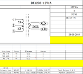
i am trying to make an 12V 1 Amps SMPS using DK1203 IC.
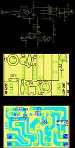
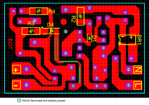
Circuit Diagram, Top Copper and Bottom Copper with component placement file has been attached.
My problem is the SMPS works well for initial 10 to 15 minutes with the load of 850mA , but later it starts flickering. i have noticed that the IC DK1203 and the transformer gets extremely hot.
The IC is recommended for upto 12 Watts output. The Transformer winding has also been made as per the transformer datasheet.
can anybody help me out where would the problem be.
 

Attachments

  • Design.jpg
    Design.jpg
    4 MB · Views: 186

DL4001 is specified at 60Hz, you need to use a fast switching rectifier.
I'm concerned the the circuit will not stabilize at 12V. It will be somewhat higher, you probably need a lower Zener voltage or it will tend to pulsate as the diode/optocoupler go in and out of conduction.

Brian.
 

Hi,

Did you read and follow datasheet?
Especially: 9. SPECIAL NOTICE FOR PBC LAYOUT DESIGN

Klaus
 

DL4001 is specified at 60Hz, you need to use a fast switching rectifier.
I'm concerned the the circuit will not stabilize at 12V. It will be somewhat higher, you probably need a lower Zener voltage or it will tend to pulsate as the diode/optocoupler go in and out of conduction.

Brian.
Yes, I have made the changes and have used SR3100 Diode instead of DL4001 and zener is 11.1V
Hi,

Did you read and follow datasheet?
Especially: 9. SPECIAL NOTICE FOR PBC LAYOUT DESIGN

Klaus
yes, i have followed the rules, as per the datasheet.
i agreed that the track was quite close to IC pin 7 and 8 as marked in the image, but have removed the track and add temperory jumper. (Image attached)
But still the problem is the same.
--- Updated ---

DL4001 is specified at 60Hz, you need to use a fast switching rectifier.
I'm concerned the the circuit will not stabilize at 12V. It will be somewhat higher, you probably need a lower Zener voltage or it will tend to pulsate as the diode/optocoupler go in and out of conduction.

Brian.
I have recently tested the system by changing the zener diode from 11V to two zener diode in series 6.8V and 3.9V. the output volt i am getting is around 11V and the temperature is also being maintained at around 40 to 45 Degree. but when i add single 11V zener, the temperature rises.
 

Attachments

  • DK1203 SMPS.png
    DK1203 SMPS.png
    98.1 KB · Views: 135
Last edited:

Hi,
What is your drain voltage spiking up to?
Also, what is the turns ratio?
Also, did you sandwich wind the transformer?
What size wire did you use for the transformer?

What does your primary current pulses look like?

To see them, get a diff probe, then solder say a 1 ohm resistor in series with the primary, just upstream of it. Put the black probe on the non transformer side of the resistor.
Do you see triangles or trapezoids, and not ski-sloping waveforms?

DK1203

(BTW, i dont think your PCB features regulatory isolation distance)

I hoep you are careful not to touch the live mains.
 
Last edited:

Hi,
What is your drain voltage spiking up to?
Also, what is the turns ratio?
Also, did you sandwich wind the transformer?

What does your primary current pulses look like?

To see them, get a diff probe, then solder say a 1 ohm resistor in series with the primary, just upstream of it. Put the black probe on the non transformer side of the resistor.
Do you see triangles or trapezoids, and not ski-sloping waveforms?

DK1203
Have attached the transformer winding details.

did you sandwich wind the transformer?
did not get your point.
 

Attachments

  • DK Trans.png
    DK Trans.png
    33.5 KB · Views: 121

did you sandwich wind the transformer?
did not get your point.
Read AN16 by power integrations.....EDIT___>

...sorry , i meant AN18, its better


You must wind the transformer interleaved....usually secondary between two primary halves...this reduces leakage inductance....if you dont do this you get too many leakage inductance related losses.
 
Last edited:

Read AN16 by power integrations.....EDIT___>

...sorry , i meant AN18, its better


You must wind the transformer interleaved....usually secondary between two primary halves...this reduces leakage inductance....if you dont do this you get too many leakage inductance related losses.
Yes, i am sure for the winding as you mentioned. secondary winding has been sandwich between two primary
--- Updated ---

but why is it that the temperature remains maintained if output voltage is less than 11V by changing the zener voltage to 10.3V
 

Is your transformer saturating...as discussed in post #5 above, it gives a way to scope the transformer primary current, so you can see if its saturating.
Also, what is the voltage on your RCD clamp capacitor when you are on full load? (use a diff probe to measure it)
 

Is your transformer saturating...as discussed in post #5 above, it gives a way to scope the transformer primary current, so you can see if its saturating.
Also, what is the voltage on your RCD clamp capacitor when you are on full load? (use a diff probe to measure it)
Sorry I don't have a diff probe to measure it.
But I have a doubt regarding Transformer saturation.
Test 1
Zener Volt 11V
Output voltage: 12.30V
Load. 1 Amps
Temperature: Around 90 degree

Test 2
Zener Volt 11V
Output voltage: 12.3V
Load. 0.650 Amps
Temperature: again Around 85 degree.

Test 3
Zener Volt 6.9V + 3.9V in series
Output voltage: 10.9V
Load. 1.2 Amps
Temperature: Around 45 degree

This are some tests I have made. And have also tested that in all the cases the max Load what I can connect is upto 1.5 Amps.

As far as what I understand is
Transformer saturation is the stage
Where transformer's core is fully magnetized and is producing maximum magnetic flux.
So in TEST 1 and 2 if transformer is saturating at 1 Amps then how is it still delivering current upto 1.5 Amps.
 

So in TEST 1 and 2 if transformer is saturating at 1 Amps then how is it still delivering current upto 1.5 Amps.
...because its just saturated m some more at 1.5A...the gap in the transformer means the saturation is gradual, not sudden
Do you actually have a gap in the transformer?
What is you transformer core?
What is the gap size?
What is Np/Ns?
What size wire?
 

...because its just saturated m some more at 1.5A...the gap in the transformer means the saturation is gradual, not sudden
Do you actually have a gap in the transformer?
What is you transformer core?
What is the gap size?
What is Np/Ns?
What size wire?
the gap between the transformer bobbin after winding and core is around 0.5mm
Have uploaded the transfomer winding details in Post No #6.
 

What is your mains voltage input?
--- Updated ---

Attached is your flyback in the LTspice (free download for you)
So:
Do you deffo use ultra fast diode for RCD and output?
What is the current sense threshold of the control chip?
Di the secondary deffo get wound inbetween the two primary halves.
 

Attachments

  • 12W FLYBACK _0FFLINE.zip
    10.1 KB · Views: 90
Last edited:

What is your mains voltage input?
--- Updated ---

Attached is your flyback in the LTspice (free download for you)
So:
Do you deffo use ultra fast diode for RCD and output?
What is the current sense threshold of the control chip?
Di the secondary deffo get wound inbetween the two primary halves.
Mains input 220v AC
For RCD have used FR107 Fast recovery diode and for output its schotty diode.
The ic does not have any current sense pin,
Yes Secondary winding is being sandwich between two primary
 

OK thanks, how are you measuring the temperature that you are seeing?
Temperature GUN.
I point the gun on IC and transformer to measure the temperature.
Even I have noticed that i cannot touch the IC and transformer for more than 5 to 6 seconds.
 
Last edited:

You mean one of those infra red pointers, or a thermal camera?.....the infra red pointers are very poor....the Thermal cams are good but you may set the wrong emissivity and they are bad.

Touch for 5 to 6 seconds....but that could mean 50-55 degC....depending on your finger skin ruggedness.
 

we are using infra red pointers.
Agreed that the infrared pointers are very poor. but then too i can expect the tolerance of 4 to 5 degree.
Than too the temperature is quite high around 85 degree when the ambient is around 24 degree.
 
Can you do an efficiency test?
Lets get a hang on what the actual losses actually are.
To measure power input, you will need a power meter. Do you have one?
Without a power meter, you have to measure the input mains current RMS value.
Then find the power factor.
Then do VAC(rms) * IAC(rms) * power factor.

Hang on ...sorry, to make this easier......can you put a very large input capacitor (electro) at the input so that your DC bus is pretty flat voltage wise.....then you simply measure the rms current input, and take vin as being the DC bus volts.

Then do P(out)/P(in)

To make things really easy for you.....you can use two big electro caps at the input....and then measure the current at the point between them...that way, the current there will be pretty flat DC and easy to measure.

Do you see what i am trying to get at here?...i am trying to make it easy for you to measure input power by making it a simple VDC * IDC measurement.

(we'll ignore the losses in the diode bridge and inrush resistor for now)

So there are many ways to do this.....you could just use a big electro cap to give you a stable VDC input...then use a sense resistor to gauge the input current...but if its got high frequency in it, you could in fact filter this out of the sensed voltage with an rc filter, and then you can do a nice, easy VDC * IDC measurement to get power input vaule.
 

Status
Not open for further replies.

Similar threads

Part and Inventory Search

Welcome to EDABoard.com

Sponsor

Back
Top