Continue to Site

Welcome to EDAboard.com

Welcome to our site! EDAboard.com is an international Electronics Discussion Forum focused on EDA software, circuits, schematics, books, theory, papers, asic, pld, 8051, DSP, Network, RF, Analog Design, PCB, Service Manuals... and a whole lot more! To participate you need to register. Registration is free. Click here to register now.

SMPS - help me add extra filtering to reduce ripple/noise

Status
Not open for further replies.

jamesdeen

Newbie level 4
Joined
Oct 22, 2012
Messages
7
Helped
0
Reputation
0
Reaction score
0
Trophy points
1,281
Activity points
1,354
Hi everyone, long time lurker here and first time poster.

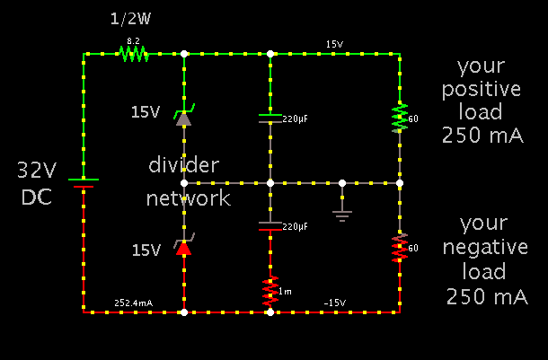
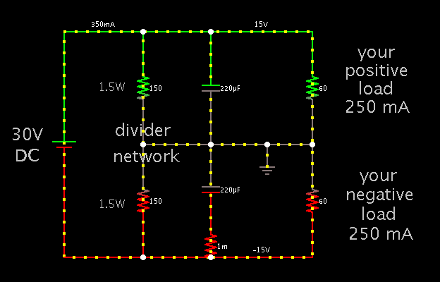
I'm working on an audio project where I need a split power supply (+/- 15V) and I need to use a SMPS in this case.

I'm not comfortable designing my own split SMPS, and I've noticed that there are several encapsulated board mount DC-DC converters with split output... which is perfect!

Most that I'm looking at spec ripple at 50mVp-p and noise at 150mVp-p like this example: https://www.cui.com/Product/Power/Dc-Dc_Converters/Isolated_Board_Mount/10_W/VYB10W_Series

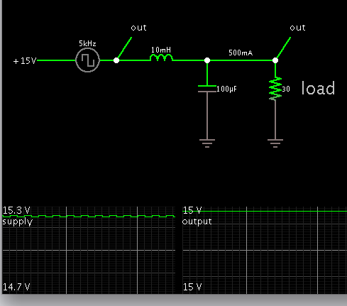
I'd really like to get the ripple and noise lower since this is an audio project. Someone suggested adding an RC then an LC then an RC filter to make a 3-stage filter, I believe he saw something similar (or even more stages) in an SMPS powered audio mixer. Is this an ideal solution, if so, can someone please walk me through the calculations for the components of that filter. Or are there other options?

In case some extra info helps: Current draw will be around 250mA per rail. Space isn't an issue in the design. Unfortunately, yes, it has to be a SMPS, with an input voltage appropriate for a wallwart (smps or linear I suppose), or 110/220VAC mains.

I hope I have all the info there, cheers and greetings,

Mike
 

Do you have an existing positive supply?

Would it be suitable if you could derive a negative power supply from that? There are circuits that can do that.
 

Do you have an existing positive supply?

Would it be suitable if you could derive a negative power supply from that? There are circuits that can do that.

Hi Brad, no I do not have an existing positive supply.
 

Hi Brad, no I do not have an existing positive supply.

The reason I asked is because all the supplies at your link take a DC voltage. None take mains AC.

I suppose you plan to obtain two supplies: one producing positive DC, and the second an SMPS to split it into a bipolar?

Going back to your initial question about filtering...

The specs they give for noise and ripple are supposedly worst case. With luck, the unit they send you will be better than the specs.

If you find it has too much noise, then a single smoothing capacitor may be sufficient. Say 1000 uF.

If that is insufficient then you can add a coil before the cap.

As in this schematic.

6046883200_1350929663.png


The supply is 15VDC, with square waves added to mimic a noisy supply.

The load is 1/2 in case you would obtain split positive and negative rails from this supply.
 

The reason I asked is because all the supplies at your link take a DC voltage. None take mains AC.

I suppose you plan to obtain two supplies: one producing positive DC, and the second an SMPS to split it into a bipolar?

Going back to your initial question about filtering...

The specs they give for noise and ripple are supposedly worst case. With luck, the unit they send you will be better than the specs.

If you find it has too much noise, then a single smoothing capacitor may be sufficient. Say 1000 uF.

If that is insufficient then you can add a coil before the cap.

As in this schematic.

Thanks for the reply Brad,
Sorry if it was confusing. You're right, I'm trying to use a single output external SMPS wall wart going into the encapsulated dual output SMPS which would be inside the unit.

If you don't mind, can you explain to me how you determined the values for the capacitor and inductor? Is it making a high-pass filter? Apologies for not knowing this stuff..

According to the datasheet, it says not to add more than 220uF per rail because "If
the capacitance is too big, a startup problem might arise."

Is there anything stopping me from adding extra filtering in addition to the LC filter you've shown on the schematic? Since this is an audio application and space and number of components aren't an issue, I'm wondering how far I could go with filtering this? I'd love to get the noise down to 20mVpp.

Thanks again for the help so far.

Mike
 

Thanks for the reply Brad,
Sorry if it was confusing. You're right, I'm trying to use a single output external SMPS wall wart going into the encapsulated dual output SMPS which would be inside the unit.

If you don't mind, can you explain to me how you determined the values for the capacitor and inductor? Is it making a high-pass filter? Apologies for not knowing this stuff..

According to the datasheet, it says not to add more than 220uF per rail because "If
the capacitance is too big, a startup problem might arise."

1000 uF is a ballpark figure for a smoothing capacitor in a power supply. It is large enough that it will help maintain volt level during brief high current draw, at the current draw you are discussing.

However if a lower capacitor value is recommended in the instructions, then use that. The reason is that a large capacitor can draw a large inrush current on power-up, interfering with the internal oscillator of the power supply.

A coil-input filter (choke) is sometimes used. It improves performance, although coils get inconvenient to make or obtain. I chose a value that seemed to work in my simulation. Resonating action can occur and if possible it should be designed to be below the audible range.

Is there anything stopping me from adding extra filtering in addition to the LC filter you've shown on the schematic? Since this is an audio application and space and number of components aren't an issue, I'm wondering how far I could go with filtering this? I'd love to get the noise down to 20mVpp.

Thanks again for the help so far.

Mike

Another thing you might consider is to split a 30V supply into +15 and -15, using a resistor divider (left) or zener regulated divider (right):

 
Another thing you might consider is to split a 30V supply into +15 and -15, using a resistor divider (left) or zener regulated divider (right):


If I split a 30V single supply, I'd still need to filter it. I'm also noticing that external SMPS outputting 30V (or 32V as shown in your zener regulated schematic) aren't easily available, which is really important.
 

It should not be hard to carry out your initial plan.

An internet search will turn up more information.

Example, below is a link to the Elliott Sound Products website. It contains numerous projects and articles geared to the audiophile.

He requests that anyone linking to his site have it go to his homepage. (Click Projects, then Power Supplies.)

**broken link removed**

I did not find a specific article on the method you are thinking of, but the articles can provide guidelines.
 

Status
Not open for further replies.

Similar threads

Part and Inventory Search

Welcome to EDABoard.com

Sponsor

Back
Top