Continue to Site

Welcome to EDAboard.com

Welcome to our site! EDAboard.com is an international Electronics Discussion Forum focused on EDA software, circuits, schematics, books, theory, papers, asic, pld, 8051, DSP, Network, RF, Analog Design, PCB, Service Manuals... and a whole lot more! To participate you need to register. Registration is free. Click here to register now.

SMPS feedback loop doesn't depend on topology?

Status
Not open for further replies.
T

treez

Guest
Newbie level 1
Hello,

Please could you help to define what circuit elements are (and which are not) in the feedback control loop of this SEPIC LED driver…………….

https://i46.tinypic.com/jttquc.jpg

V(in) is fixed at 6V.

Input current is regulated by the loop.
Output voltage could be anything between 5V and 40V.
Input power is limited to 7W.

The converter is a SEPIC , but I believe that the actual converter topology could have been anything, and the control loop would not change…is this true?

I mean, the converter’s power stage and output capacitors simply are not in the feedback loop…do you agree?
The feedback loop simply involves the input capacitors..is this true?
 

The topology(Buck, Boost, or SEPIC) is part of the feedback loop, but not whole.
 
  • Like
Reactions: treez

    T

    Points: 2
    Helpful Answer Positive Rating
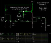
When I have experimented with simulations of various SMPS's, I find a buck converter lends itself to a simple on-off control circuit. It just needs a feedback wire to an op amp, with hysteresis.

However I find that the other types (boost, etc.) require at least two avenues of control.
(1) The coil must be switched on, and it must be switched off, which requires its sense/feedback circuit.
(2) Then there is the voltage/current on the load, which requires its sense/feedback circuit.

I have not found a way to make them work with a simple op amp using hysteresis. Of course I'm only a hobbyist, so don't take my word as final.
 
  • Like
Reactions: treez

    T

    Points: 2
    Helpful Answer Positive Rating
The topology certainly affects the transfer function of the converter, regardless of exactly what you define as your input and output. Even if most of the converter circuitry doesn't appear to be directly in the path of the "loop," it still affects the loop behavior. Doing the math reveals how.

I have not found a way to make them work with a simple op amp using hysteresis. Of course I'm only a hobbyist, so don't take my word as final.
Direct hysteretic control can work with buck and boostbuck derived topologies, but not boost or buckboost topologies. This is because buck/boostbuck converters deliver power to the output while the switch is on. This allows direct-hysteretic feedback to be stable.
 
Last edited:
  • Like
Reactions: treez

    T

    Points: 2
    Helpful Answer Positive Rating
Even if most of the converter circuitry doesn't appear to be directly in the path of the "loop," it still affects the loop behavior

The point is that completely removing the output capacitors doesnt make it go unstable. I think only the primary inductor of the sepic inductor appears in the feedback loop. Do you agree?
 

The point is that completely removing the output capacitors doesnt make it go unstable. I think only the primary inductor of the sepic inductor appears in the feedback loop. Do you agree?
No, of course not. The rest of the converter shapes the transfer function of the input current. Whether the changes actually make the converter unstable can't be determined without proper analysis. It may ultimately turn out that the effect of the load or topology is not very significant, but you can't simply assume that with nothing to back it up.
 
  • Like
Reactions: treez

    T

    Points: 2
    Helpful Answer Positive Rating
It may ultimately turn out that the effect of the load or topology is not very significant, but you can't simply assume that with nothing to back it up.

I would say that with the complete removal of the output caps, and that stability was "not" worsened by this drastic act, speaks volumes that the output caps do not have a part to play in the feedback loop equation...surley you agree?....i mean, try and stabilise an output voltage regulated smps with no output capacitance.

If nothing else, surely you agree that total removal of all output capacitance is a pretty drastic action to take with an smps.
The fact that it had no effect tells you a lot, surely?
 

It is possible to operate a buck converter without a smoothing capacitor. Perhaps also the SEPIC converter.

It can be done by increasing the frequency, so that the coil is in continuous conduction mode. One could say it starts to resemble choke operation, as it stores and releases energy.

Simulation of a buck converter without a smoothing capacitor:


Notice the operating frequency is high for a 1 mH coil. It will get faster if the regulation is made tighter, since the hysteresis loop must become narrower.

The other types (boost, buck-boost) require a load capacitor. It must be there to absorb what comes through the coil during one half of the cycle, then it must be there to power the load as it discharges.

From my experiments with simulating a SEPIC converter, it has several components that can smoothe to some degree, without needing a smoothing capacitor in some cases.
 
  • Like
Reactions: treez

    T

    Points: 2
    Helpful Answer Positive Rating
Status
Not open for further replies.

Similar threads

Part and Inventory Search

Welcome to EDABoard.com

Sponsor

Back
Top