Continue to Site

Welcome to EDAboard.com

Welcome to our site! EDAboard.com is an international Electronics Discussion Forum focused on EDA software, circuits, schematics, books, theory, papers, asic, pld, 8051, DSP, Network, RF, Analog Design, PCB, Service Manuals... and a whole lot more! To participate you need to register. Registration is free. Click here to register now.

Slowly charging capcitor with Solar Energy and then using it as a source...please see

Status
Not open for further replies.

navienavnav

Member level 1
Member level 1
Joined
Dec 12, 2011
Messages
36
Helped
1
Reputation
2
Reaction score
1
Trophy points
1,288
Location
India.
navneetkhare.co.cc
Activity points
1,627
I have a solar panel which is successfully able to run a small DC motor that I have as long as it is under direct sunlight. If not, it is unable to drive the motor (for example, in the presence of artificial light). What I am trying to do here is to charge a capacitor using the small current (slowly and over some time) which the solar panel produces under artificial or low light and when the capacitor is fully charged, AUTOMATICALLY make the motor run using the energy stored in the capacitor for a second or two and then again, AUTOMATICALLY, the capacitor should restart charging itself using the solar energy.

So the motor would run and then stop and then run and then stop over time as the capacitor charges and discharges.

Is it possible to do so using a capacitor without manually having to disconnect the solar cell when capacitor is charged and then connecting the capacitor with the motor? When I was a little I once had seen a small solar powered robot toy on Discovery Kids TV Channel which worked like that so I think it might be possible...

Can you help? :D
 
Last edited:

you can use comparator. to check the voltages across capacitor. if voltages are enough to satisfy need of motor swtich on the transistor to supply from capcitor and if voltages goes down comparator will toggle the transistor againg to cut the supply.

- - - Updated - - -

you can use comparator. to check the voltages across capacitor. if voltages are enough to satisfy need of motor swtich on the transistor to supply from capcitor and if voltages goes down comparator will toggle the transistor againg to cut the supply.
 

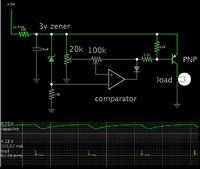
Possible solution using comparator, as posts 3 and 4 mention:


I made assumptions about the volt level of the system, and the power drawn by the motor.

The zener diode creates a voltage differential at the comparator input. This allows you to use capacitor voltage as a power supply for the comparator.

Adjust the 100k potentiometer to create the desired voltage swing on the capacitor.

The simulator supports an op amp but not a comparator. That is the reason for the diode pointing toward the output. If you use a real comparator then you can omit the diode and substitute a plain wire.

If you use an op amp then its output must go high enough to turn off the PNP transistor.
 
This circuit will consume all the current from solar cell and nothing will be left for charging capacitor. Remember the initial problem is to charge capacitor in dark conditions. I assume we are talking about currrents of mA or less. To give some exact answer, we need info about solar cell: voltage and power!!!
 

This circuit will consume all the current from solar cell and nothing will be left for charging capacitor. Remember the initial problem is to charge capacitor in dark conditions. I assume we are talking about currrents of mA or less. To give some exact answer, we need info about solar cell: voltage and power!!!

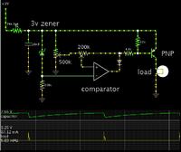
I increased all resistor values. Now it does not lose as much current.

If the panel puts out 1 or 2 mA, then charging the capacitor takes a much longer time. About 160 seconds.

Successful operation requires that the capacitor be in excellent condition.
Electrolytics are known to develop leakage between the plates. (The likelihood goes up with age and Farad value.) At 20,000 uF, it may have a tiny current leaking through. This could prevent its charging to a sufficiently high level.

- - - Updated - - -


Thank you for all the replies. I'll definitely try this once my exams are over... The comparator one.

P. S. The open terminal voltage that i measured of the solar panel using multimeter under direct sunlight was about 5.8 v and the current through the multimeter was (when it was the only load) about 250 mA.
 

Status
Not open for further replies.

Part and Inventory Search

Welcome to EDABoard.com

Sponsor

Back
Top