Continue to Site

Welcome to EDAboard.com

Welcome to our site! EDAboard.com is an international Electronics Discussion Forum focused on EDA software, circuits, schematics, books, theory, papers, asic, pld, 8051, DSP, Network, RF, Analog Design, PCB, Service Manuals... and a whole lot more! To participate you need to register. Registration is free. Click here to register now.

Sinking 5V Powered LEDs from 3V MCU

Status
Not open for further replies.

ngmedaboard

Member level 3
Member level 3
Joined
Feb 7, 2010
Messages
60
Helped
7
Reputation
14
Reaction score
4
Trophy points
1,288
Location
United States
Activity points
1,831
I think I've answered this same question before but I forget the answer.

I want to confirm it's safe to sink a 5V powered LED through a 3V MCU.

Depending on how the output pins are pulled up or down, I'm concerned about seeing a small reverse leakage current when the output is high (3V) and the LED is tied to 5V. There should be very little current flowing other than leakage? Just want to make sure this is a safe configuration.
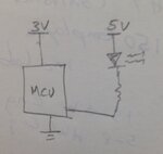
3V_5V_MCU_LED_PWR.jpg

Thanks
 

Hi,

i´d use a logic level MOSFET like BSS138.

Gate to uController,
Source to GND,
Drain to Resistor -> LED -> 5V

Klaus
 

yes use transistor as level shifter and interface transistor with led and use it in switching mode.
 

The LED does not detect reverse voltage until about 5v to 7v - no-one has realised this.
 

As above mentioned,you can't do this.
it is not allowed to connect two different voltage level.
You should use a transistor or MOSFET to as level shifter.
 

As above mentioned,you can't do this.
it is not allowed to connect two different voltage level.
You should use a transistor or MOSFET to as level shifter.

Where do you get this RUBBISH from ?????
 

If you use a standard output from the MCU you should make sure that the 'high' or OFF level are not pulled up with the LED.

This may be a problem for a red LED, but to be on the safe side, you just add one or two diodes in series with the LED to increase the voltage drop.
You need to recalculate the resistor to take the lowered available voltage into account, 0.6 - 0.65V per diode you put in.

If the LED has a Vf of >2V you should not need any correction, and your circuit is ok.

Another thing is that you should take care not to power the 5V circuit, without powering the the 3V circuit. If you do that the 3V circuit will be supplied through the output back wards, and this may damage your microcontroller.

If there is a possibility for this, use a transistor to drive the LED.
 
Last edited:

Another thing is that you should take care not to power the 5V circuit, without powering the the 3V circuit. If you do that the 3V circuit will be supplied through the output back wards, and this may damage your microcontroller.

How did you work that out ???

I am amazed at the absurdities conjured-up by the readers of these forums.
For a start, the LED will have a characteristic drop of nearly 2v across it before ANY current flows and if a small current flows via the current-limiting resistor, it will flow through the protection diode (on the top and bottom of all inputs of a microcontroller).

It's obvious from what you say that you have not backfed an integrated circuit from an output, or input for that matter. Most unpowered circuit does not like this, and you may get an unwanted effect from a circuit partly powered, if you apply the normal power supply.

It's in no way an absurdity, and it's a good design practice to be aware of the possibility to do damage, and even create the magic smoke, if Murphy will.

With those characteristics you deliver in abundance, it could be interesting to know your background.
It is easy to denigrate others attempt to help people, not so easy to help yourself?
 
Last edited:

You are talking about generalities and I am talking about specifics.
The two are entirely DIFFERENT.
In this case above we are talking about currents less than 20mA. Don't confuse the issue.
 

If you read the PIC datasheet you'll see that the abs max i/o clamp current is +/-20mA. In my book the general picture also includes the specific cases, even if you get away with it, at times.

And there is no confusion of any issue here. What I try to advertise is a good design philosophy, even if the posters on the forum is not going to do this as a living.

Of course you can provide your entire encyclopedic philosophy to a simple request, but all he wants to know is the potential of catastrophic failure when adding the LED to the 5v supply.

The maximum current will be 20mA when the line is pulled LOW. At any other level the current will be less than 20ma. Many LEDs are now active at 3mA to 10mA and over-bright at 20mA. In this case it will be less than 20mA.
 

Hi,

yes, the base resistor is a good hint.

* with a mosfet you don´t need a resistor. (but the problem is when port is floating - maybe during reset - the led state is not predictable)
* there are so called "digital transitors" with built in 1 or 2 resistors.

Klaus
 

Hi,

yes, the base resistor is a good hint.

* with a mosfet you don´t need a resistor. (but the problem is when port is floating - maybe during reset - the led state is not predictable)
* there are so called "digital transitors" with built in 1 or 2 resistors.

Klaus

Just wanted to point out the importance of the part I highlighted and underlined in the above quote. Oh how important it is to include that resistor. I've had countless drivers and MOSFETs blow into smoke because I didn't put a pull-down resistor since I expected the driver to pull down the gate.
 

Status
Not open for further replies.

Similar threads

Part and Inventory Search

Welcome to EDABoard.com

Sponsor

Back
Top