Continue to Site

Welcome to EDAboard.com

Welcome to our site! EDAboard.com is an international Electronics Discussion Forum focused on EDA software, circuits, schematics, books, theory, papers, asic, pld, 8051, DSP, Network, RF, Analog Design, PCB, Service Manuals... and a whole lot more! To participate you need to register. Registration is free. Click here to register now.

Single ultrasonic transducer switching between Rx and Tx

Status
Not open for further replies.

Huixin Zhang

Newbie level 2
Newbie level 2
Joined
Jul 22, 2014
Messages
2
Helped
1
Reputation
2
Reaction score
1
Trophy points
3
Visit site
Activity points
15
Hi,
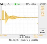
I am trying to use one ultrasonic transducer for RX and TX. The transmitted signal was 25 KHz square wave from Arduino Uno, and the switch is controlled by Arduino. The result is shown as the following picture.
1.jpg
The four cycles of square wave is the transmitted signal and after that it is the received signal. My question is: why the amplitude of the received signal is greater than the transmitted signal? Thank you very much.
 

It looks as though you found the natural resonant frequency of the transducer... correct?

As for the return image, it reminds me what happens when you push a pendulum to the right 5 inches, then let go.

The pendulum swings to the left maybe 4 inches. Therefore the overall amplitude is 9 inches, even though you only moved it 5 inches initially.

You pushed the transducer toward the positive only, but the return image caused it to ring in both the positive and negative.
 
The crystal piezo device is also a resonator, which may have a voltage gain greater than unity in the passband.

But power cannot be increased by a passive echo.

The source Tx and load Rx impedance changes also from low to high on the same port so reflections are lower (current) energy, even if the same voltage. Thus what you would see if it were terminated with a low impedance is a drastic attenuation of the reflected signal power.
 
The energy decay in a resonant item decays at 1/Q per cycle, so with a ulltra sonic transducer with a Q of 20,000, it will take a long time for the energy to decay. It could be interesting if after the transmit cycle a dead short was put across the transducer to try to dissipate the energy quickly, before switching it to the receive cycle.
Frank
 

My question is: why the amplitude of the received signal is greater than the transmitted signal?
The amplitude isn't larger. That's a misinterpretation due to comparing square wave and sine peak voltage. In fact the corresponding fundamental wave Vpk of a square wave is 4/pi = 1,27 * square magnitude.

Terminating the transducer with a matched resistive load can achieve a faster oscillation decay.

I wonder if the signal in the post #1 wavefom shows actually an echo or just the decay of the high Q transmitter oscillation? We should know the setup.
 

Status
Not open for further replies.

Part and Inventory Search

Welcome to EDABoard.com

Sponsor

Back
Top