Continue to Site

Welcome to EDAboard.com

Welcome to our site! EDAboard.com is an international Electronics Discussion Forum focused on EDA software, circuits, schematics, books, theory, papers, asic, pld, 8051, DSP, Network, RF, Analog Design, PCB, Service Manuals... and a whole lot more! To participate you need to register. Registration is free. Click here to register now.

[SOLVED] Single power supply instrumentation amplifier using LM324

Status
Not open for further replies.
@KlausST
however please help me clear some of my doubts (it may sound stupid but please...)
1. what was wrong with the earlier chosen values for differential voltage simulation; i.e. in post #16 (except placement of 4K resistor)? It was made for 0-150mV.
2. Still with this set up I get gain of 10 for voltages above 50mV. Why not for voltages <50mV?
3. Why 4K only? How can I calculate which value is to be used? Because it is difficult to find the resistor of 4k & 36K in electronics market!
4. How can I add offset at the output?
5. Can you suggest me a further reading on the subject so that I can improve myself?

Thanks & please make me understand the things.
@crutschow: Thanks buddy. But I would not like to loose my focus from the ongoing discussion right now. Though I appreciate your help.
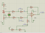
 

Problem is that you did not manage to generate the correct input voltage in your previous simulation, which must have common mode around 2.5V (Vcc/2) as the bridge sensor has. Instead you are using unsuitable high resistor values and an asymmetrical voltage divider.

To understand why the expected gain isn't achieved, observe the voltage at OP input terminals and compare with specified input voltage range in datasheet. It's specified as 0..Vcc-1.5V, which is 0..3.5V for 5V supply. Due to the asymmetrical divider, the 3.5V limited is probably exceeded. I'm presuming so far that the Proteus LM324 model has correct common mode range, must not necessarily be so.
 
Hi,

1) the problem is the source impedance of the "simulated sensor".
To be exact: the source impedances don't match
And what makes it worse: it changes with changing the pot value.
The symmetry is essential for generating the exact "difference".

With unknown, unsymmetric, varying or high source impedance you need the true instrumentation amplifier circuit. It rectifies the problems with impedance, bacause the input impedance of the first (two) stages is very high, while the output impedance is very low.

2) what setup are you speaking of? If #18, then the expected unlinearity for 0mV ...100mV input is less than 1%.
Offset errors (this is not unlinearity) may be caused by Opamp input offset voltage and opamp input offset current.
Real unlinearity may be caused because the Opamp can't drive it's output to exactely 0V.
Therefore the recommendation to add 50mV or more offset voltage.

3) 4k is the value given by the sensor (4k....6k). 500Ohms are added by the two 1k resistors. Now we have about 4500 ohms.
Meaningful resistor values are 4k....5k to get good sensor simulation.
The sensor source impedance causes gain errors (no unlinearity). Now that you (very late) said that you need absolute accuracy with a sensor source impedance of 4k..6k --> you need the complete instrumentation amplifier circuit.
(Usually with pressure sensors one has the chance to calibrate gain with software. As soon as you can calibrate gain with software you don't need absolute accuracy anymore. Precision (good linearity, low drift, low noise) is sufficient. Then you can use the simple difference amplifier circuit. You have to decide)
At the sensor datasheet there is no specification about absolute accuracy.
But there you see that a simple difference amplifier is sufficient.
(One remark to the datasheet: from the circuit it has not a true mV output, but a ratiometric output with 1-2mV/V full scale. As long as your ADC uses the same 5V as reference it does not harm)

4) I recommend to use a 10k/ 100R voltage divider. It generates 50mV at the center. Now disconnect R4 from GND but connect it to this 50mV node. This introduces small errors, about 0.25% of the 400k. No need to worry as long as your 400k resistor is 1% tolerated.

5) application notes. Especially from Opamp manufacturers (like TI, LT, AD..) I'm sure you find something about "pressure sensors", "strain gauge sensors" or similar.

Please give the updated schematic with offset and a table of the results.

Klaus
 
@KlausST
1. OK I got it.
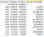
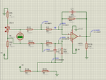
2. But what if my sensor has output voltage from 0-50mV only? (not in this case but may be in future!). Since current setup (refer below simulation picture & table) gives me non-linear output for vin<50mV; how should I deal with this? Please say more about this.
3. I think You cleared my confusion about absolute & precision accuracy. So precision will be sufficient for me.
4. Yes I have done that and posted in my comment (see below).
5. Surely I need some more googling. Thanks for this.
PLease see the results.
ckt3.png
tab1.png
 

Hi,

The results show that the output is not pulled to GND as expected.
* either this is a simulation problem
* or we dont have the correct situation.

Looking into the datasheet it says:
Output Voltage Swing VOL / V+ = 5 V, RL = 10 kΩ / 5 / 20 mV

The 10k is to GND. The current is 20mV/ 10k = 2uA.
Now in your circuit you have a 400k to 2.5V, this gives additional 6.25uA.

You need a minimum Vout of 50mV...at (2uA + 6.25uA), this means a pulldown of about 6k (max. --> use 4k7)

Now do a new set of measurements...but with an additional 4k7 resistor from opamp output to GND.
Let's see if this gives the expected values.

Klaus
 

It's true that a pull-down can further reduce the minimal output voltage in real LM324 designs. But as Proteus has obviously a faulty LM324 model, I won't expect correct results in this case.
 

Hi,

I don't have proteus, so I can't test it. But I'd give it a more than 50% chance that the pulldown works.

My idea: I assume the simulated (and maybe the true ) device can not actively drive the output very close to GND.
(In datasheet they "improved" the ground rail capability by adding a resistor to GND)
In the TI datasheet there is the LM324 inside schematic. Two paths can drive te output to GND.
* Q13 - controlled by Q12 - is limited to drive only to maybe 0.55V to GND, closer is not possible
* and a 50uA current source.....but I doubt that a simple semiconductor current source can drive closer to GND.

...I'm curious about the simulation results...

Klaus

Btw: The LMV324 seems to be a "true" RR output opamp.
With a realistic load condition: "R_L= 10 kΩ to VS/2". So the Opamp needs to drive actively close to both rails.
 

@crutschow I agreed your setting: the input common mode voltage is 2.5V and the output is offset to 2.5V. It is important to the whole simulation result because the voltage at any key points would be far away from zero and power rail.
 

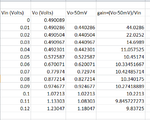
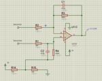
@KlausST: I have done simulation with the 4.7K at the opamp output. where i got the same results for Vin<50mV, Please refer below circuit & results.
However, I got a chance to simulate my circuit on NI Multisim and it shows almost correct values of gain & output wrt differential input voltage. Does it draw any conclusion? Like may be as FvM said it may be problem of proteus simulation for LM324?

ckt2.png
tab2.png
 

HI,

I agree, this might be a Proteus simulation problem. I can´t think of any other cause.
But the good news: I think the results on a real circuit are much better.

Your table shows a deviation of about 7% from 50mV input to 120mV input. In reality I expect it to be better than 1%.

****
How do you go on now?
* Using this circuit?
* using another OPAMP? --> I expect improvements
* using LM324 with negative supply? --> I expect improvements

Klaus
 

Hi KlausST hope you and everybody here having good weekend!

*Yes I will be using this circuit, based on the results i am getting on real hardware. Will keep posted.
*Can you suggest any other amplifier? which can work on single supply? With better specs?
*No, I cant use dual supply.
I really appreciate help provided by dear forum members and happy to part of you guys! Cheersss....

However, I have 2 doubts:
1. I will be using this circuit now on breadboard; I think i dont have to use that 4K resistor from the legs of 50E. Those were only to simulate the differential voltage obtained from sensor. In real hardware, sensor itself provide that impedance (4k...6k). Correct me if I am wrong. I am posting here schematic:
ckt4.png

As we discussed it is good to start with resistor 10X greater that the impedance provided by sensor. So in that case combination of 47k, 470k or 68k & 680k or 100k & 1M will also provide gain of 10. BUT....BUT what these different values will have effect on output? or they will not affect it? What points i must consider while choosing these value? It should be larger or smaller.....what criteria?
2. And you asked to put the cap of 470pF across resistors to reduce noise problems. As per my understanding you must calculated that using formula; fc=1/(2*pi*R*C). But how can I determine my fc here? Would be helpful if you can make it more simpler if possible.
Thanks.
 

Hi,

* What´s wrong with the suggested LMV324?
* 4k are for sensor simulation only. But it influences accuracy as written above.
* larger value resistors will introduce more noise and will introduce more output offset voltage caused by I_offs x R_fb
* fc is given by your application. YOU need to decide. I´ve given examples.
Klaus
 

Actually I have lm324sn in my stock. Looking for LMV324 for availability in market. And thanks for clearing all other points too.
Planning to get the project on workbench by next week. Will keep you posted.
Thanks again friends for your valuable time.
Thanks KlausST.
 

Status
Not open for further replies.

Similar threads

Part and Inventory Search

Welcome to EDABoard.com

Sponsor

Back
Top