Continue to Site

Welcome to EDAboard.com

Welcome to our site! EDAboard.com is an international Electronics Discussion Forum focused on EDA software, circuits, schematics, books, theory, papers, asic, pld, 8051, DSP, Network, RF, Analog Design, PCB, Service Manuals... and a whole lot more! To participate you need to register. Registration is free. Click here to register now.

Single phase vfd for split air-conditioner

Status
Not open for further replies.

ramjee2001

Newbie level 2
Joined
Sep 12, 2015
Messages
2
Helped
0
Reputation
0
Reaction score
0
Trophy points
1
Activity points
19
I have a 1.5 tonnes split air-conditioner running in my office. I made some refrigeration circuit modification and eliminated the starting current ( I am a ref.techie BTW :smile:). Now the unit starts at
5 Amps and smoothly coming to rated current of
8 Amps. Now my aim is bringing down the rated current to 6 Amps without compromising performance. This is possible only by introducing a single VFD.

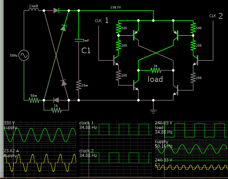
Can anybody suggest me a cost effective electronic circuit with single phase 230 V input and output where I can adjust output frequency between 35 Hz to 50 Hz...? The circuit should be good for 10 Amps.
 

1.5 tonnes is equivalent to ~ 1.65 tons which (as I recall from my computer room ACU design days) takes about 1650 Watts to drive. (10xton=kW)


1650W/230=7.17A so 6A is undersized and 8A ensures it runs near full RPM under extra load from recycling while still warm which drops down, fairly quick. (~10 s)

Lowering startup current increases the startup time and increases winding temperature rise during startup.
 

A straightforward way to reduce the AC current consumption is to adjust the expansion valve for lower refrigerant mass flow.

Single phase motors aren't well suited for variable frequency operation, 35 Hz might work though. And I'm not aware of any commercial single phase VFD. Technically, it's 2/3 of a 3 phase inverter, so using an industry standard 230V 10A VFD is the next best solution.
 

This concept works theoretically. In hardware it will require robust components.

Rectify and filter mains AC. Feed the DC to an H-bridge at 35 Hz.


Square waves are not the best waveform for AC motors. Therefore you probably would add an LC filter (series, or 2nd order low pass type) which can shape a square wave into a sine wave of greater amplitude.
 

Thanks everyone for responding. @BradtheRad... Can you please give me the values/part# of the all the components, so that I try to get assembled..? I want to adjust the output frequency between 35Hz to 50Hz.
 

My schematic is a theoretical concept, rather than being complete and ready-to-build. It lacks many details. It may even be totally unrealistic.

Example, can your mains AC provide pulses of 23A? Would a circuit breaker trip?

This amount of Amperes should not be applied to a single capacitor, but should be shared by a bank of capacitors. Can you obtain sufficient capacitors which are rated for 400VDC? (Because voltage will rise to 330V when there is a light load.)

High voltage is an obvious risk. As well as the risk of ruining a big expensive air conditioner.

A motorized appliance can generate spikes, back-EMF, etc., which could ruin the H-bridge mosfets.

If a short-circuit were to happen for any reason, it would expose the air conditioner to high voltage DC. I have not heard of this being tried, but I believe it would destroy the appliance.

Also consider what others have replied above. They are more expert than me.
 

Status
Not open for further replies.

Similar threads

Part and Inventory Search

Welcome to EDABoard.com

Sponsor

Back
Top