DeepOne
Advanced Member level 2
- Joined
- Feb 26, 2011
- Messages
- 632
- Helped
- 99
- Reputation
- 200
- Reaction score
- 100
- Trophy points
- 28
- Location
- 45N39E, Russia
- Activity points
- 0
Follow along with the video below to see how to install our site as a web app on your home screen.
Note: This feature may not be available in some browsers.
experimental designs usually feeding through resistor or light bulb for current restriction.it has broken all mosfet
You may try circuit with STM8S003 from message #393.circuit so much that I hardly choose
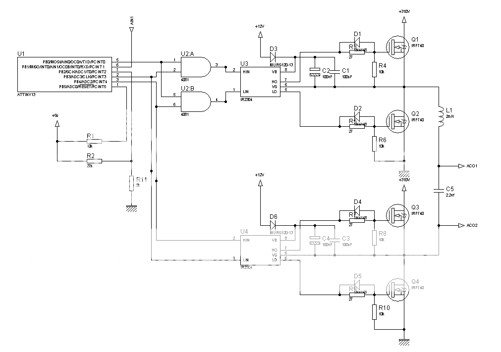
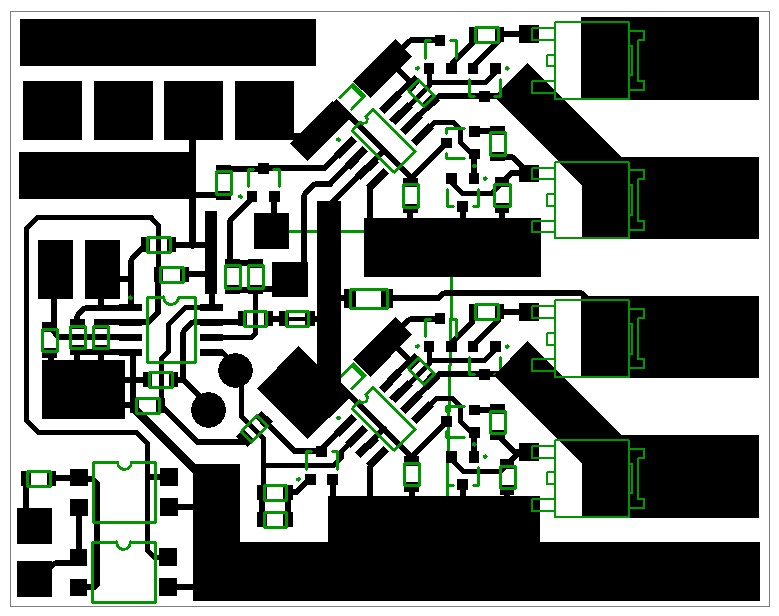
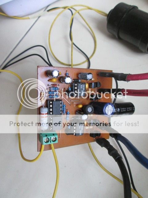
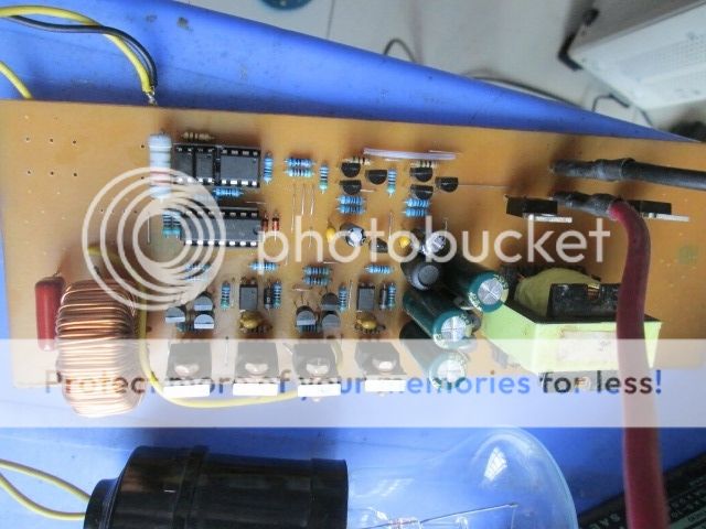
ir2304 not very good for this, because it's deadtime only 100ns, but beside me was not nothing better.I will fix the PCB to mount v.4
hardware debugger is much more suitable for mcu designing than Proteus.I can simulate with Proteus but with STM8S
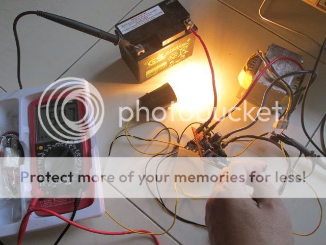
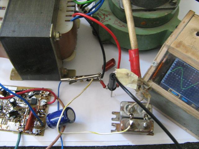
may be around 0,7A from 1,5A is output capacitor recharging current.When transformer connecting the board and no load is 1.5A
You may try circuit with STM8S003 from message #393.
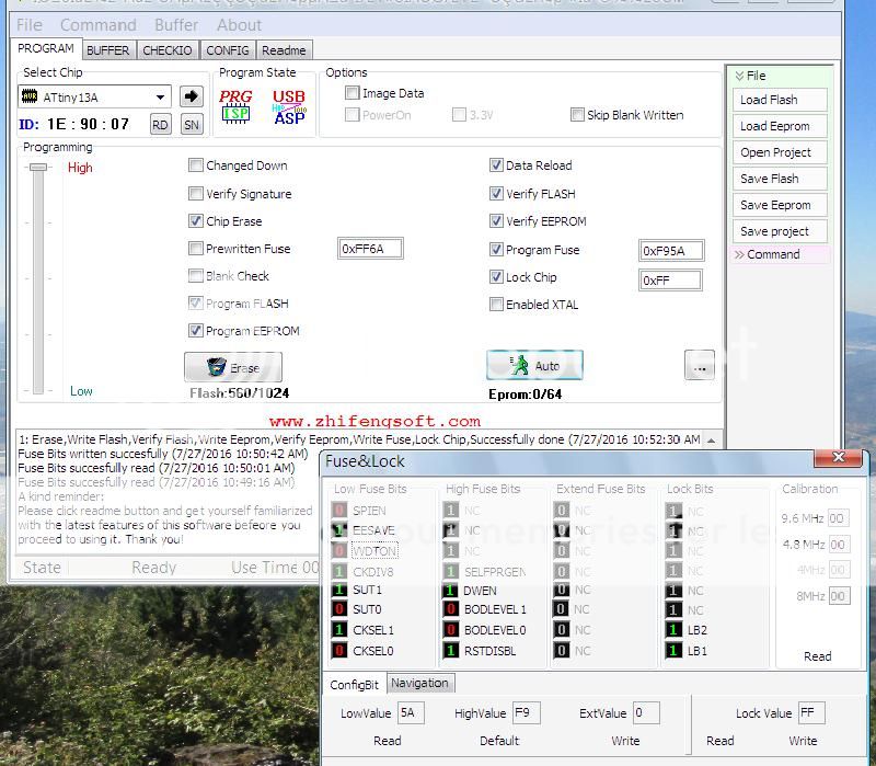
that is practically impossible because that is not output of pwm timer. You may use any external DC-DC and not connect this pins.correct the firmware so that the legs 7 and 8 of the MCU clock is 50-100Khz.
You mean circuit from message #326? or something else?What is the features & Specification of this inverter?