Continue to Site

Welcome to EDAboard.com

Welcome to our site! EDAboard.com is an international Electronics Discussion Forum focused on EDA software, circuits, schematics, books, theory, papers, asic, pld, 8051, DSP, Network, RF, Analog Design, PCB, Service Manuals... and a whole lot more! To participate you need to register. Registration is free. Click here to register now.

[SOLVED] Sine Wave Inverter - noisy output (LF) transformer

Status
Not open for further replies.
R

red_alert

Guest
Newbie level 1
I've just tested my 2kW pure sine wave inverter and it's working just fine except a powerful audible noise from the LF (50Hz) output transformer.

I'm using a sPWM driven H-bridge to convert 24V DC to 16V AC then I'm using a step-up LF transformer to rise the AC to 230V. The transformer is from a broken UPS (APC Smart-UPS 1500).

I'm using an unipolar sPWM signal and I've tried different sample rates (carrier frequencies) - like 5kHz, 10kHz - but I've got the same(?) noise.

Unfortunatelly, I don't have an oscilloscope right now to look for the waveforms so I'm asking you guys if you have any clue about what's going on.

The humming/buzzing noise seems unchanged with or without (full) load. I'm using a 2uF capacitor in parallel with secondary (230V) winding. The primary (16V) winding is directly connected to the H-bridge output without any other filter (capacitor, inductor).

The inverter's design looks similar to APC UPS I've just mentioned earlier - even the output capacitor was used in the APC design.

I forgot to mention that the transformer it's not getting warm or something.. neither the MOSFETs (even at full load) but the noise it's very powerful and I'm worried about it.
 

check for a lose lamination in the transformer core?
Mik
 

    V

    Points: 2
    Helpful Answer Positive Rating
Ah, perhaps you have a (shifting) Dc bias current (net average) on the primary that is going from pos to neg and back at some frequency - a lot of newish inverter designers eventually realise you have to control the DC applied to the LF transformer if you don't want a lot of DC to flow. Lets say the primary DC res is 0.002 ohm and you have a net DC offset (that varies) of 20mV - that is 10 amps of DC in the pri which will easily saturate the Tx.
You may have lesser amounts, but they may well be there and changing or oscillating (from near Bsat one way to the other, etc)

Food for thought...?

Regards, Orson.
 
  • Like
Reactions: Anna Conda

    Anna Conda

    Points: 2
    Helpful Answer Positive Rating
    V

    Points: 2
    Helpful Answer Positive Rating
check for a lose lamination in the transformer core?
Mik

Thanks for the tip, Mik!

It just didn't crossed my mind to check that because I've just pull the transformer from an "just died" UPS. I've just thighten up the screws (they were pretty lose indeed) and the noise has reduced alot! Now I can finally "listen" the high frequency whining though the lower frequency noise it's still there.

Does the output capacitor (across the output) has something to do with it? Do I have to put a larger one, if the carrier frequency might be lower than the original (APC) design?

LATER EDIT:

I've checked the transformer (after thightening up the screws) WITHOUT the output capacitor (and load). As far as I connected the capacitor, the powerful noise has return. :((

So it's something related with the output capacitor. It's value is 2,2uF/400V. Is it too small/large? Unfortunatelly, I don't have such spare capacitors to test different variants.

PS:

Thanks for the tip, Orson! I don't have the possibility to check the DC bias current but I'm confident that the sPWM signal it's quite simetrical and the MOSFETs are identical (and no one is getting hot). Like I've just said, the noise comes out when I connect the output capacitor (with or without load).

Maybe it's some kind of (bad) resonant frequency, I should try with different capacitor values.
 
Last edited:

It is a typical MOSFET powered H-bridge, nothing fancy. Actually, the whole circuit it's described in the following image:

Unipolar sPWM - transformer type.jpg

You can see the output (filtering) capacitor I'm talking about. I'm still turning my home upside down trying to find some spare capacitors to make some tests. ;)
 

You need to look across the cap with a scope when running to see if you can see the freq of the "noise" (although it may be hard to see).
Your switching may be kicking off a resonance between the cap and the magnetising L of the transformer.
Usual solution is an RC snubber across the cap (Cs = 5~10 times the cap value, R = what works, although R = SQRT(Lmag/C) is a good starting point.
 
  • Like
Reactions: Anna Conda

    Anna Conda

    Points: 2
    Helpful Answer Positive Rating
    V

    Points: 2
    Helpful Answer Positive Rating
I've tried with a second (identical) transformer with the same results. Moreover, I've tried with two different transformers (from other pure sine wave UPS, rated for 500W and 750W) and I've got the same powerful noise when I put the output capacitor.

I even tried with a different capacitor (1uF, PP X2 class) but nothing has changed. Perhaps I should try your solution (a RC snubber) but I don't know how to measure the magnetising L of the transformers. Can you point me to an usual R value to start with and it's power ratings (watts)?

Like I said, I don't have a (functional) scope right now so i'll have to go with blind tests. Maybe I should put some kind of snubber circuit (or capacitor) across the primary winding (between H-bridge legs)?
 

i think snubber circuit always use at secondary winding of transformer parallel to load . . .
 

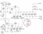
Well, take a look at this APC Smart-UPS schematic diagram:

APC-Smart-UPS-snubber.jpg

Anyway, I've tried it but I had no luck with it either.
 

i am still confuse why snubber is used in input side of transformer . what are the advantages of it to be place here ??? may be they are considering transformer as load ??
 

Anyway, I've tried it but I had no luck with it either

So you tried ~20uF and 47 or 100 ohm say (100 - 200W), across the offending cap to damp out whatever is occurring?

L(230v side) will be in the order of 1.8H, so the res freq with your 2.2uF cap at 80Hz, which is not too far from 50Hz, if the L(230V) is a bit bigger, you will be closer to 50Hz which explains the 50Hz loud noise...! too close to resonance means lots of AC circulating current and noise.

1st step: Make the C size smaller so the res is 1/10th of the sw freq say 500Hz, well above 50Hz, say100nF (275Vac) and have a listen.

Orson.
 
  • Like
Reactions: Anna Conda

    V

    Points: 2
    Helpful Answer Positive Rating

    Anna Conda

    Points: 2
    Helpful Answer Positive Rating
Many thanks, Orson!

No, I've just tried the APC's snubber network (from bridge output to ground). I just can't wait to try your suggested solution and I'm pretty sure it will cure my problem. Have a nice day!
 

It worked like a charm!.. Orson, you're the man! Now I just love that 10kHz whining.. ;)

But I still wonder why APC used that capacitor (2.2uF) anyway.. it might be part of a mains EMI filter for the situation when the UPS is working as a battery charger (I must admit I didn't have time to accurately read the PCB traces).
 

i am confuse that what is the role of snuber here from bridge out put to ground ??
 

Actually, in the APC design, there's a snubber from each bridge output to the ground. Maybe it's some kind of low-pass filter, to prevent high frequency (switching) harmonics to reach the LF transformer.
 

Glad your current problems are solved, the snubber from the middle of a fet half bridge to ground is there to reduce overshoot and ringing at no load, which ends up on the transformer output.
Orson.
 
  • Like
Reactions: Anna Conda

    V

    Points: 2
    Helpful Answer Positive Rating

    Anna Conda

    Points: 2
    Helpful Answer Positive Rating
Status
Not open for further replies.

Similar threads

Part and Inventory Search

Welcome to EDABoard.com

Sponsor

Back
Top