michcfr
Advanced Member level 4
Hello,
I have created a Proteus model implementing a Press-ON-Press-OFF push button according to the first schematics of this page:
 www.mosaic-industries.com
The Microcontroller is replaced by the LED10 to show Power on/off and SW2 for the I/O pin to reproduce manually the I/O
www.mosaic-industries.com
The Microcontroller is replaced by the LED10 to show Power on/off and SW2 for the I/O pin to reproduce manually the I/O
What I expect:
.short button press of SW1: LED ON
.and another short button press of SW1 toggles it back OFF
What I get:
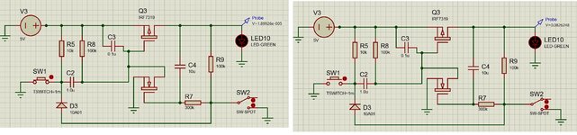
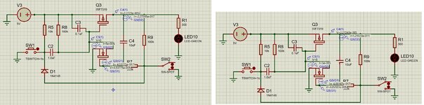
.short button press of SW1: LED OFF. See the left picture of the attached file. The Probe is at almost 0V
.and another short button press of SW1: LED OFF. See the right picture of the attached file. The Probe is 0.0826V
Can you please help me to debug the Proteus model. Thx
Regards,
Michel
I have created a Proteus model implementing a Press-ON-Press-OFF push button according to the first schematics of this page:
Push Button ON-OFF Toggle Switch and Latching Power Circuit for Microcontrollers
A simple latching high side soft power switch toggles ON and OFF microcontroller based products and instruments, including single board computers and raspberry pi or arduino boards. A short button press applies power, a subsequent press initiates orderly shutdown under control of the...
www.mosaic-industries.com
What I expect:
.short button press of SW1: LED ON
.and another short button press of SW1 toggles it back OFF
What I get:
.short button press of SW1: LED OFF. See the left picture of the attached file. The Probe is at almost 0V
.and another short button press of SW1: LED OFF. See the right picture of the attached file. The Probe is 0.0826V
Can you please help me to debug the Proteus model. Thx
Regards,
Michel