Continue to Site

Welcome to EDAboard.com

Welcome to our site! EDAboard.com is an international Electronics Discussion Forum focused on EDA software, circuits, schematics, books, theory, papers, asic, pld, 8051, DSP, Network, RF, Analog Design, PCB, Service Manuals... and a whole lot more! To participate you need to register. Registration is free. Click here to register now.

simulating Oxide capacitance (Cox), mobility of charge carriers in NMOS and PMOS

Status
Not open for further replies.

viperpaki007

Full Member level 5
Joined
Jul 2, 2008
Messages
270
Helped
11
Reputation
22
Reaction score
8
Trophy points
1,298
Location
Finland
Activity points
3,395
Hi,

How can i simulate the values of Oxide capacitance (Cox) and mobility of charge carriers in NMOS and PMOS in cadence. These values are not provided in process design kit file.

regards
 

You would have to do basic simulations to find those.

Do the Id-Vgs and Id-Vds simulations to find the kn/kp parameters.
Do the Capacitance simulations to find out Cox.
And hence find the mobility.
 

Thanks....I have understood how to find out Kp and Kn values but then how to simulate Cox?
 

For measuring Cox, Put the Drain and Source at GND and Put a DC source at Gate such that the device is in strong inversion. Now put an ac source at the Gate and measure the capacitance. This would be Cox.

This is described in Razavi page 38.
 
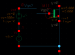
In order to find the Cox, I simulate this circuit:

In fund 20fF with a W and L of 2µm. The Cox should then be 5fF/µm. Is it a correct value for the 90nm techno? On Martin's book, Cox = 4.5 for 0.35µm, 8.5 for 0.18µm and 25 for 45nm. Regarding these values, I should get something like 12fF, No??

thank you
 

Attachments

  • Cox.png
    Cox.png
    14.2 KB · Views: 170

Are you using a core device or a high voltage device?

The core device would be the default device with lower max voltage around 0.9V/1V. This would have higher capacitance and is of the order of 12fF/µm2.
The higher voltage device like a 3.3V device would have lower capacitance and is around 5fF/µm2.

So what you have quoted is the correct value but not for the correct device.
 
I think you're right. I'm using 3.3V devices, and this is the lowest Cox of the library.

I've 4 differents kinds of MOS: std vt with 34.7fF/µm², high vt with 27fF/µm² and veryhigh vt with 57fF/µm². But these 3 have a leakage of tens of pA!
The last one I'm using is a std vt 3.3, with 5fF/µm² with no leakage (in the simulation).
But I'm not able to find a device with a 12fF of Cox.

Anyway, it's quite and easy way to find the oxyde capacitance of a MOS.

- - - Updated - - -

well, actually it depends on the voltage applied to the grid...
 
I'm simulated the Cox with a dc at 1V and AC 1mV. I'm getting a peak to peak current and I'm using the formula : Cmos = WLC_{ox}. Am I right?
Just wondering because this peak to peak current is different for an other DC voltage and depends on the Veff.
Here is the plot of the current from -2 to 3V. Where is the correct point for the Cox calculation?

thanks
 
For calculating Cox, you should do the measurement when the device is in strong inversion. So that would mean that the gate voltage would have to be the max.
If you see Razavi p39, you would see the Gate Capacitance vs Gate Voltage charaterestics.

The accumulation region cap need not be the same as the inversion region capacitance.
 
Yes, I was looking for the plot in the Razavi's book, but in the martin's book (p59) it's quite the same, unless the equation is Cmos_ON = WLCox + 2WLovCox.
So I was just wondering if the capacitance I simulated could be extract from this simple equation: Cmesured = WLCox.
 

Thanks, everything's clear!

From Martin's book: C_mos_ON = WLCox + 2WLovCox and C_mos_OFF = 2WLCovCox... Then, we can use the curve I plotted to find Cox = (C_mos_ON - C_mos_OFF)/WL !!

I got C_mos_OFF = 3.33fF and C_mos_ON = 6.8fF. So the Cox = 3.47fF... (with W and L = 1µm)
 

Hi,

I found another way to calculate Cox of the process. In the device model parameter, oxide thickness is given. Moreover, oxide permittivity is also given as 3.9..oxide capacitance can be found by Cox =(eo. er)/tox. Where eo= free space permittivity. eo=oxide relative permittivity and tox is oxide thickness.
 

Status
Not open for further replies.

Part and Inventory Search

Welcome to EDABoard.com

Sponsor

Back
Top