analog_ambi
Member level 1

- Joined
- Jul 19, 2011
- Messages
- 39
- Helped
- 1
- Reputation
- 2
- Reaction score
- 1
- Trophy points
- 1,288
- Activity points
- 1,560
Hi,
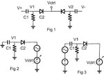
a) I am designing a LC vco and using the varactor shown in fig. 1 where C is mim cap and C2 is diode varactor
Resistor sets the node V1 near 0V.
b) I want tuning range from 786Mhzz to 800Mhz which requires C to change from 1394f to 1342f i.e. delta_C=52f
My doubts:
1. How C1 and C2 and Resistor should be chosen/ratio? I know C1 should be very large.
2. I want to check the standalone equivalent capacitance through simulation using AC 1V, freq=1/2pi,sweeping DC volt across varactor (Method by Ken Kundert) .The varactor alone works fine.
3. But the cap of combination is not C1 series C2 . Instead in Fig.2 it is C1 and in Fig. 3 it is C2. The node V1 seems to be an AC ground thereby preventing series combination of C1 and C2.
My question is how this circuit works? Am I doing mistakr by simulating this way?
