juz_ad
Full Member level 2

- Joined
- Dec 17, 2011
- Messages
- 130
- Helped
- 0
- Reputation
- 0
- Reaction score
- 0
- Trophy points
- 1,296
- Activity points
- 2,541
Hello,
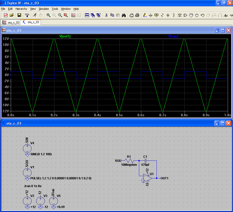
Can anyone explain the behaviour of this integrator simulation - it's not as I expected.
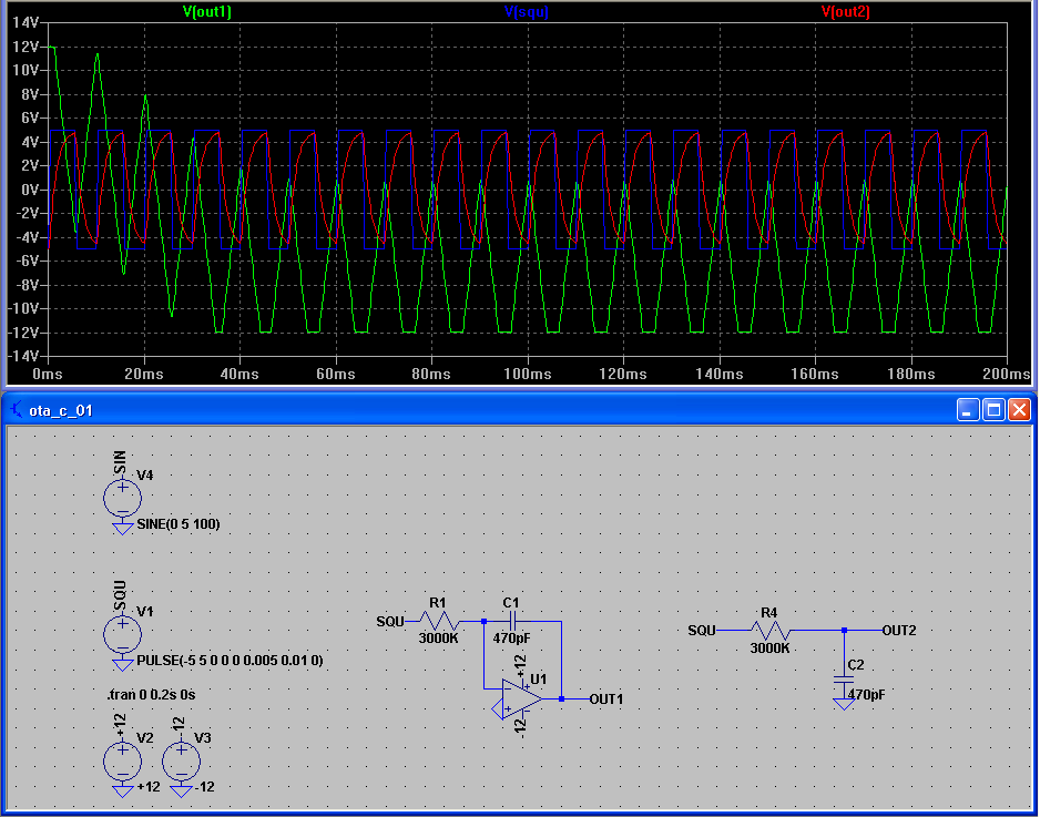
There is an active and a passive integrator, they both use a +/-5V square wave @ 100Hz as the input.
The output of the passive integrator is doing what I expected - but the output of the active integrator swings down between the negative rail and 0V - why is this?
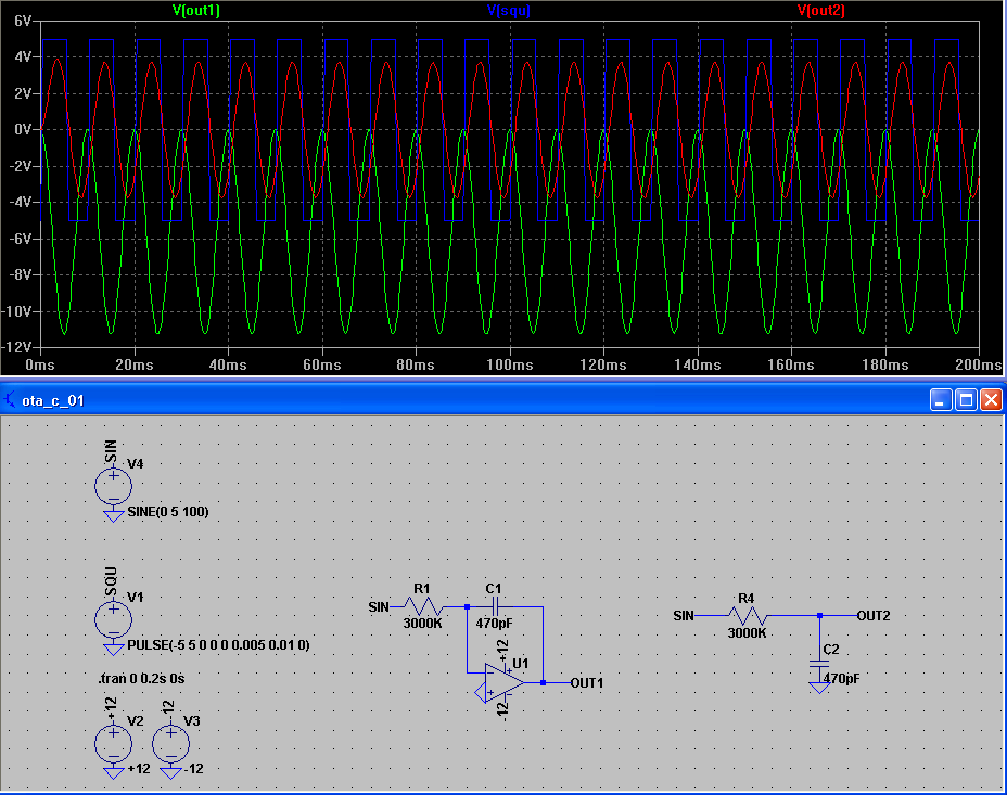
I also notice that if I use a 100Hz Sine as the input - the signal goes straight to 0V to -12V - why is this?

Thanks!
Can anyone explain the behaviour of this integrator simulation - it's not as I expected.
There is an active and a passive integrator, they both use a +/-5V square wave @ 100Hz as the input.
The output of the passive integrator is doing what I expected - but the output of the active integrator swings down between the negative rail and 0V - why is this?
I also notice that if I use a 100Hz Sine as the input - the signal goes straight to 0V to -12V - why is this?
Thanks!