Continue to Site

Welcome to EDAboard.com

Welcome to our site! EDAboard.com is an international Electronics Discussion Forum focused on EDA software, circuits, schematics, books, theory, papers, asic, pld, 8051, DSP, Network, RF, Analog Design, PCB, Service Manuals... and a whole lot more! To participate you need to register. Registration is free. Click here to register now.

simple tube preamplifier (space charge) does not work

Status
Not open for further replies.

neazoi

Advanced Member level 6
Joined
Jan 5, 2008
Messages
4,122
Helped
13
Reputation
26
Reaction score
15
Trophy points
1,318
Location
Greece
Activity points
36,951
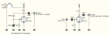
I experiment with the ECC86 tube in low anode voltage.
I have successfully built the oscillator in the left and set the capacitor for minimum distortion (and lowest signal), but the RF preamplifier in the right (around 500KHz) does not work ok.
I have tried replacing the grit resistor with a 1meg trimmer and the anode resistor with a 22k trimmer, but no matter how I set these I see no amplification but attenuation most of the times.
Any ideas what to try?
 

Attachments

  • Capture.JPG
    Capture.JPG
    43.3 KB · Views: 269

If I google "ECC86 Amplifier circuit" I see them all with cathode generated
bias.....? What is you DC grid voltage ?


Regards, Dana.
 

    neazoi

    Points: 2
    Helpful Answer Positive Rating
If I google "ECC86 Amplifier circuit" I see them all with cathode generated
bias.....? What is you DC grid voltage ?


Regards, Dana.
Dana I re-measure it and it seems it does provide amplification. This was my fault initial reading I apologize. The AGC of the receiver gave me false readings.
 
You SHOULD add bias to the second schematic or it will work as a rectifier. I would suggest adding a small resistor in the cathode (guess = 100 Ohms) and bypassing it with a ceramic capacitor. Without the small voltage drop across the cathode resistor the static grid to cathode voltage will be zero and any positive signal cycles will result in grid current flowing and hence rectification. I think I would aim for between 0.1V and 0.2V on the cathode.

Brian.
 

    neazoi

    Points: 2
    Helpful Answer Positive Rating
You SHOULD add bias to the second schematic or it will work as a rectifier. I would suggest adding a small resistor in the cathode (guess = 100 Ohms) and bypassing it with a ceramic capacitor. Without the small voltage drop across the cathode resistor the static grid to cathode voltage will be zero and any positive signal cycles will result in grid current flowing and hence rectification. I think I would aim for between 0.1V and 0.2V on the cathode.

Brian.
Ok I did so, I added a 180R parallel to a 100nF and these connected to the ground and the cathode. It did not change many things in the operation, but since you say so I leave them there. the cathode voltage is 106mV
 

Status
Not open for further replies.

Similar threads

Part and Inventory Search

Welcome to EDABoard.com

Sponsor

Back
Top