Continue to Site

Welcome to EDAboard.com

Welcome to our site! EDAboard.com is an international Electronics Discussion Forum focused on EDA software, circuits, schematics, books, theory, papers, asic, pld, 8051, DSP, Network, RF, Analog Design, PCB, Service Manuals... and a whole lot more! To participate you need to register. Registration is free. Click here to register now.

Simple linear regulator question

Status
Not open for further replies.

Wamor

Junior Member level 2
Joined
Jun 16, 2009
Messages
24
Helped
0
Reputation
0
Reaction score
0
Trophy points
1,281
Activity points
1,491
Hello,

I am experimenting with some simple electronics and have a question.
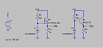
I build simple linear regulator with a transistor (see attached picture) and it works fine.
Can I replace the NPN transistor with a N-channel FET. I learned that FET's
could be a replacement for transistors. Can I replace the NPN-transistor with
a N-FET. What will be the advantages/disadvantages of this replacement.

Thank you and best regards,

Wamor
 

Attachments

  • Linear-Regulator.PNG
    Linear-Regulator.PNG
    6.4 KB · Views: 91

Instead of asking others, you can perform a simulation of output voltage versus load current or input voltage variation. LTSPICE has a DC sweep simulation for similar purposes. You'll notice, that if the BJT follower load regulation is acceptable for your requirements, the FET follower most likely isn't. So obviously, a FET isn't a good BJT replacement in this case.
 
  • Like
Reactions: Wamor

    Wamor

    Points: 2
    Helpful Answer Positive Rating
Good notice that I used LTSPICE and thank you for the answer.
I did some simulation as you suggested by replacing R3 and R4 by a current source drawing current from 0 to 500mA.
I noticed that the load regulation using a FET was better than when using a BJT. See attached picture. Do you have any explanation for this.
 

Attachments

  • Linear-Regulator2.PNG
    Linear-Regulator2.PNG
    41.9 KB · Views: 65

I noticed that the load regulation using a FET was better than when using a BJT.
The diagrams don't show this. You may want to adjust the voltage scales for comparable ranges.

What's the intended output voltage, by the way?
 

Hello,

The intended voltage is not important for me yet. I just want to learn more about BJT's and FET's.
Please find attached the scaled diagrams. Looks to me that the FET has better load regulation?

Thank you and best regards,

Wamor
 

Attachments

  • Linear-Regulator3.PNG
    Linear-Regulator3.PNG
    24.3 KB · Views: 60

Yes, you are right, the voltage variation is lower in the shown current range. I came to the same conclusion when checking the results. This is because you have selected a MOSFET with a large Idss and respective transconductance. For a real voltage regulator, you would also want a tightly tolerated output voltage, which gonna be more problematic.
 

Simple linear regulator question is put the majority of the filter capacitance. It uses a voltage reference diode, the program resistor, diode and R3 make sense.
 

I tested the FET-circuit with a 2k2 resistor and a 43V zenerdiode in order to generate a outputvoltage arround 40V with an maximum outputcurrent 250mA at 60V input voltage.
The FET I selected gets destroyed when switching an inputvoltage of 60V to the circuit. When I look in the datasheet I see that the FET I am using has a maximum Vds of 40Volts.
Could this be the cause of my problem because when switching the circuit on for the first time there could be a voltage across this FET for a short time which larger than its maximum Vds?
 

Could this be the cause of my problem because when switching the circuit on for the first time there could be a voltage across this FET for a short time which larger than its maximum Vds?
Yes, another possible reason is exceeding the maximum Vgs rating.
 
  • Like
Reactions: Wamor

    Wamor

    Points: 2
    Helpful Answer Positive Rating
Thanks a lot for the answer.
Could you maybe explain a little bit more in what situation Vgs could exceed the maximum rating?
Is this also during power-up when all capacitors are not charged yet and have a very low impedance?
 

The risk of exceeding any of the maximum ratings depends on the exact circuit, including bypass capcitors and also the load. I would however use a transistor with a Vds rating above the maximum input voltage, and place a voltage limiting zener diode between gate and source, if the input voltage is above Vgs, max (e.g. 20 V). If the circuit analysis clearly shows, that Vgs can never exceed the maximum rating, you don't need it, of course. But I would prefer, that the circuit is still safe in unexpected situations.
 
  • Like
Reactions: Wamor

    Wamor

    Points: 2
    Helpful Answer Positive Rating
Status
Not open for further replies.

Similar threads

Part and Inventory Search

Welcome to EDABoard.com

Sponsor

Back
Top