Vermes
Advanced Member level 4
It's the most useful tool in every electronics workshop. An important feature of this device is that the temperature of etching solution can be controlled with a simple driver. The system described is itself such a simple driver. There is also a possibility of a set temperature.
The first plate was made a few years ago with AT89C4051 microcontroller. Now it's better to use something newer, like Attiny 2313 because of it isn't necessary to process the already existing plate. That is how the etching tank driver was made. It has a LCD display 2x8 marks and a temperature sensor DS18B20. The actuator is triac. Controlling of the heater is done in a proportionate way by cycling turning on and off the heater at low frequency. The attitude of operating time for a break depends on the difference between the set temperature and the temperature inside the box. Because of the lack of space in microcontroller, there is no settings save into the EEPROM memory. It isn't a serious disadvantage, because in 99% cases - the temperature is set on 40 Celsius degrees.
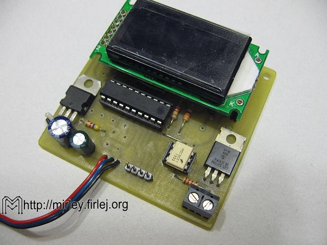
The main element of the system is microcontroller U1 (Attiny2313), working on an internal resonator, frequency of 8MHz. The alarm buzzer B1 is switched on with a T3 transistor (BC556). R1 (3,3k) improves the transistor's base into +5V, when R2 (3,3k) limits the base current. The action of the system is visualized on a small W1 LCD display (8x2).
The P1 potentiometer (10k) regulates the contrast, while the R5 resistor (510R) limits the current of LEDs structures which give the backlight. GP3 connector is useful to connect the DS18B20 temperature sensor. R6 resistor (4,7k) enables its proper action. As a keyboard connector, Gp2 connector is used. The executive circuit is executed on a Tr1 triac (BT138-600E) and an OPT1 optotriac (MOC3042). It provides the optic isolation from the voltage. The R4 resistor (220R) limits the triac gate current and the R3 (330R) limits the optotriac LED's current. The power circuit is made of U2 stabilizer (7805) and two capacitors C5 (22uF) and C4 (47uF).
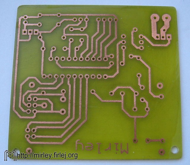
The plate showed in the pictures can be different from the one described in the scheme, because as it was mentioned above, it's an old project that was transformed. It's good to start with soldering the three jumpers, marked with red color. After that it's necessary to solder the resistors and the processor and optriac bases. The stabilizer and the triac should be installed lying down, unless the dimensions of the housing allow the vertical montage. The LCD display should be installed with use of socket drivers on headers, so the removing is easy. It is important, especially that the display contrast regulation is placed under the display itself. Sequence of other actions is optional. The system can be powered by DC 7-12V. In the model system, the 12V/1.2A power supply in the form of pulse inverter was used. The time sensor should be placed in the etching driver, so it's really important to protect its legs against the ingestion. Besides the imposition of thin heat shrinkable shirts on each leg, the whole sensor should be awashed with poxipol or another glue of that type.
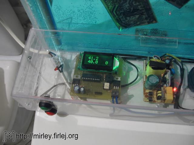
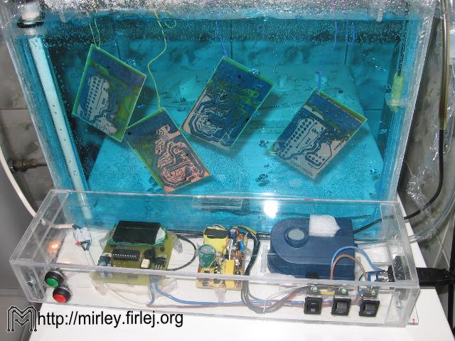
The etching driver box:
The construction of the box itself isn't complicated, but really laborious. The dimensions and thickness can differ, depending on the needs. The dimensions should allow for the placement of the plate close to A4 (3cm thick) inside the box. The housing is made of 6mm plexi. Air bubbles contribute to the etchant splashing out so it's essential to remember about the proper height of the box. It is also important when it's necessary to move the etching driver. It's easy to splash out the etchant when it almost fills the box during even a little tilt. It is good to equip the box with a lid, because that could improve the box's thermal isolation and make additional protection against splashing out. Pieces of the same plexi solved in acetone could be used to stick together each elements. In the bottom of the box, there was placed a hose with a diameter of approximately 6mm, with small holes made with a hot needle. It ensures good etching solution mixing, because of air bubbles. Inside the box, from one side, the handles for the heater were glued. The typical aquarium heater without the thermostat (300W) was vertically placed. Aquarium pump causes the temperature in whole box remained at the same level, despite this arrangement of the heater. On the other side of the box, there is the temperature sensor in a special handle made of plexi. The whole box was glued to a bigger plexiglass plate. An electronic housing made of the same material is placed near the box.
Link to original thread with some useful attachments - Prosty Sterownik Trawiarki]Prosty Sterownik Trawiarki
Last edited: