Continue to Site

Welcome to EDAboard.com

Welcome to our site! EDAboard.com is an international Electronics Discussion Forum focused on EDA software, circuits, schematics, books, theory, papers, asic, pld, 8051, DSP, Network, RF, Analog Design, PCB, Service Manuals... and a whole lot more! To participate you need to register. Registration is free. Click here to register now.

Signal level shifting from +-15 to +-25

Status
Not open for further replies.

dreambook

Newbie level 2
Newbie level 2
Joined
Mar 19, 2011
Messages
2
Helped
0
Reputation
0
Reaction score
0
Trophy points
1,281
Visit site
Activity points
1,296
I have a bipolar signal with a peak to peak voltage of 30V (+-15V). I need to shift the signal level to be (+-25) with a dual supply voltage rails of (+-25). Do you have any ideas or a circuit implementation for such a task? i need to use discrete components so i can reach a higher voltages, my signal is a square wave Bipolar 50% duty cycle and 40 kHz frequency
 

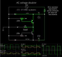
I devised this AC voltage multiplier.

By adjusting the potentiometers you can obtain a range of output amplitudes.


It consists of a positive Villard doubler and a negative Villard doubler. These are controlled by transistors which reproduce the waveform of the supply.
 
thanks Brad very much
can you provide me with the simulation files for that circuit, if i have a higher supply voltage +-25 is it better to use a level translate circuit or a sort of charge pumping circuit or voltage doubler circuit ?
 

thanks Brad very much
can you provide me with the simulation files for that circuit

The program is Paul Falstad's interactive animated simulator. Free to download and use, at falstad.com/circuit.

Or click the link below. It will open the Falstad website, load my schematic above, and run it on your computer.

https://tinyurl.com/nzshhpo

if i have a higher supply voltage +-25 is it better to use a level translate circuit or a sort of charge pumping circuit or voltage doubler circuit ?

Whichever, as long as you can obtain components which are able to endure the higher volt levels.

My schematic is based on the charge-pump made from Villard capacitor/diode pairs. One for each polarity. These double the AC volt levels.

To use my schematic, your signal needs to have low impedance.

However if your signal has high impedance, then it will not be able to drive discrete components by itself. It will need an amplifier to give it voltage gain. The amplifying device must already be supplied by the higher voltage to which you wish to boost your signal.
 

Status
Not open for further replies.

Part and Inventory Search

Welcome to EDABoard.com

Sponsor

Back
Top