Continue to Site

Welcome to EDAboard.com

Welcome to our site! EDAboard.com is an international Electronics Discussion Forum focused on EDA software, circuits, schematics, books, theory, papers, asic, pld, 8051, DSP, Network, RF, Analog Design, PCB, Service Manuals... and a whole lot more! To participate you need to register. Registration is free. Click here to register now.

Sigma delta adc design in Simulink

Status
Not open for further replies.

somyasinha

Newbie level 2
Joined
May 18, 2008
Messages
2
Helped
0
Reputation
0
Reaction score
0
Trophy points
1,281
Activity points
1,293
Sigma delta adc design

Hi,

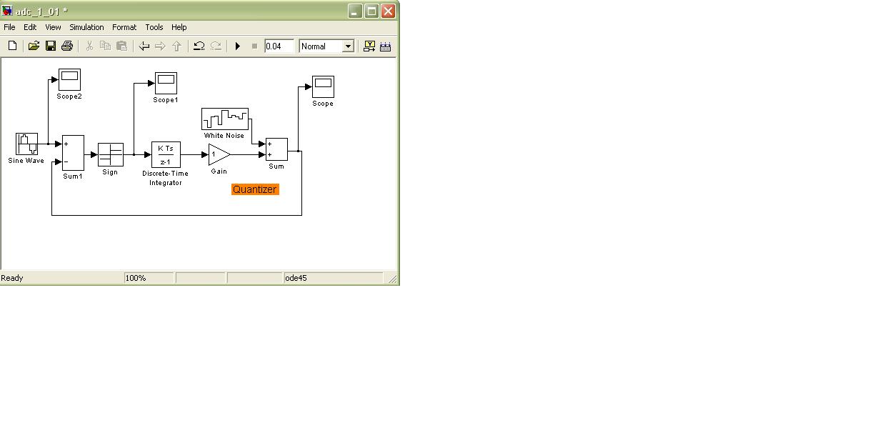
I am trying to simulate a simple first-order sigma delta ADC in simulink. I wish to know if the following block diagram is correct.

Somya


Re: Sigma delta adc design

There's no need for adding that second summer because you only add it to make analysis easier (linear) for you as a designer. Matlab has no problem analyzing non linear systems. You should add a comparator/quantizer, this will be useful for comparing your analysis to the results given by Matlab

Also why did you insert a quantizer before the integrator? That way no noise shaping will ever take place.

Bottom line : remove the 2nd summer and the white noise blocks, remove the quantizer placed before the integrator, and place a quantizer after the integrator and you got yourself a delta sigma modulator.

This link has video lectures concerning Delta Sigma Modulators, you'll also find some simulink simulations in the slides

**broken link removed**
 
  • Like
Reactions: ahm55

    V

    Points: 2
    Helpful Answer Positive Rating

    ahm55

    Points: 2
    Helpful Answer Positive Rating
Status
Not open for further replies.

Part and Inventory Search

Welcome to EDABoard.com

Sponsor

Back
Top