Continue to Site

Welcome to EDAboard.com

Welcome to our site! EDAboard.com is an international Electronics Discussion Forum focused on EDA software, circuits, schematics, books, theory, papers, asic, pld, 8051, DSP, Network, RF, Analog Design, PCB, Service Manuals... and a whole lot more! To participate you need to register. Registration is free. Click here to register now.

setting a low-pass filter

Status
Not open for further replies.

Dinkleberg

Newbie level 2
Newbie level 2
Joined
Feb 3, 2013
Messages
2
Helped
0
Reputation
0
Reaction score
0
Trophy points
1,281
Visit site
Activity points
1,299
Hi everyone,

For a project, I need to build a low-pass filter and connect it to the end of a high-pass filter and get a bandpass. The high-pass is already built and I am not allowed to do any changes on it. The bandpass I'll get must allow frequencies from 100Hz to 5kHz to pass. I simulated different combinations on lt spice but no luck so far. When I get the bandwith right, the amplification is wrong(about -50dB). I'd really appreciate any help on how I should build a low-pass there.

There's the built hpass. Uout is the output and the reference is M2. "Ub"s are supply voltage of the opamps. As you might guess MIC replaces a microphone that can produce max ac 0.5V. Unfortunately I didn't get any screenshots of my nearly succesful low-passes. They were damping every signal anyway...

hpass.png
 

Hi everyone,

For a project, I need to build a low-pass filter and connect it to the end of a high-pass filter and get a bandpass. The high-pass is already built and I am not allowed to do any changes on it. The bandpass I'll get must allow frequencies from 100Hz to 5kHz to pass. I simulated different combinations on lt spice but no luck so far. When I get the bandwith right, the amplification is wrong(about -50dB). I'd really appreciate any help on how I should build a low-pass there.

There's the built hpass. Uout is the output and the reference is M2. "Ub"s are supply voltage of the opamps. As you might guess MIC replaces a microphone that can produce max ac 0.5V. Unfortunately I didn't get any screenshots of my nearly succesful low-passes. They were damping every signal anyway...
Hi Dinkleberg
For desinging a first order high or low pass filter , you can easily use transfer function . but when you're going to combine two filters together , you've to consider more parameters . for example phase margin of your filters and impedances of course .
on of the simplest ways is using a buffer between each filter then there won't be any special problem .

Let me bring you an example , for a 1st order LPF with op amp ( like a miller integrator ) you can easily use this formula ( i.e while your input is a sine wave ) ( if you've an op amp with a capacitor in feedback path which is in parallel with a resistor and a resistor as zin ) :
If we call feedback impedance as Z2 and input resistance as Z1 we'll have this : H(s) = -(Z2s/Z1s) so because Z2 is complex you can easily derive cut off frequency through it .
Z2 is Sc*R2/Sc+R2
for sine wave S= j omega . so you can easily take cut off from it with your desired gain .
Best Wishes
Goldsmith
 

1.

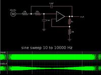
Here is a typical lo-pass configuration built around an op amp.


The scope trace shows how a sine sweep responds.

This is a second order filter. It may or may not have a sufficiently steep rolloff curve for your purposes. You may want to look into third order, etc.

This link has more info:

https://www.electronics-tutorials.ws/filter/filter_5.html

2.

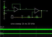
I am experimenting with a simulation of your high-pass filter. It appears to have no effect in the range 1k to 20k.


For a project, I need to build a low-pass filter and connect it to the end of a high-pass filter and get a bandpass. The high-pass is already built and I am not allowed to do any changes on it. The bandpass I'll get must allow frequencies from 100Hz to 5kHz to pass.

Hi Dinkleberg,

if my understanding is correct, you simply need a lowpass with 100Hz cut-off frequency (because you are not allowed to modify the existing high pass at all), correct?
Thus, I do not care about the high pass and simply ask:
* Which low pass order (n=1 or n=2) ?
* Gain requirements (active or passive)?
* In case of active: Single or dual supply?
 

Thanks for the replies everyone. I experimented a little more and got what I wanted. I still appreciate your time though.
 

Hi again
I need to improve what i've wrote above .
1- Phase margin is not important in design process . i've tried to focus on impedances which are complex . that was my mistake .
2- About using buffers ,active filters don't require buffers , but it is one of the ways that can improve the design for people that are not able to match impedances together but in fact that's not a good way .
3- i've told miller integrator . but in fact miller integrator don't have any resistor in parallel with the capacitor . ( now i know it has been called damped integrator )
4- H(s) = -(Z2(s)/Z1(s)) my mean is Z in laplacian .
Here some interesting articles about filter design are coming :
**broken link removed**

or :
**broken link removed**
or :
http://hobbyelectron.blogspot.co.uk/2011/05/first-order-low-pass-filter.html

or : ( this is very interesting )

**broken link removed**

Best Wishes
Goldsmith
 

Status
Not open for further replies.

Part and Inventory Search

Welcome to EDABoard.com

Sponsor

Back
Top