Vermes
Advanced Member level 4

It is a simple system for servomechanisms control, which can be used in a model railway. The assumption of this design was to create a driver that can set a servomechanism in two positions with fixed speed. Parameters of operation (0 and 1 position, speed) should be easy to be changed.
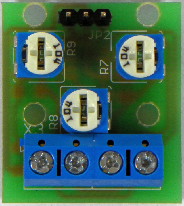
The driver allows for control only one model servomechanism. System sets the servomechanism in two positions which can be controlled by user with fixed speed. Regulation of both positions and speed can be done by assembly potentiometers.
When the power is on, driver is set in 0 position, which can be controlled using the left potentiometer. When it is changed to 1 position, it can be controlled by the right potentiometer. Servomechanism speed while changing the position can be controlled using the bottom potentiometer.
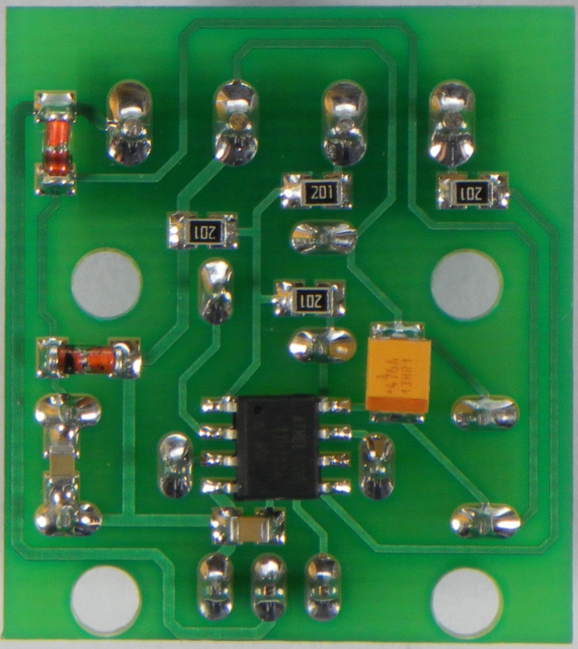
Construction:
Main element of this simple construction is cheap and easily available microcontroller AVR TINY13. All outputs together with reset were used in this design, so the system has to be programmed in HVISP mode. Power supply consists of polarization protection in the form of diode D1, protection from too high voltage (Zener diode D2) and supply filtering capacitors. Potentiometers sliders were connected directly to ADC inputs of the microcontroller. System is equipped with two inputs MODE1 and MODE2. MODE2 reponds to shorting to the ground and is configured as an input with pullup. Resistor R1 is a protection. MODE1 is connected to the input of the AC converter. During normal operation, voltage at this input is equal to the half of the supply voltage determined by R3, R4 divider. When you short that input to the ground, there is a drop of voltage, while when it is shorted to the supply, there is an increase. In that way you can plug two buttons to one input of the microcontroller.
Note that at this way of plugging the buttons (one to the supply and another to the ground) you should use a 100ohm resistor connected in series to each of the buttons in order to protect from simultaneously pressing them.

Handling:
Change of position of the servomechanism can be implemented in two ways:
- two buttons, using the A input – shorting that input to the ground (0V) causes the servomechanism transition to the 0 state, whicle shorting to the supply (5V) results in changing into 1
- one button, using the B input – each shorting the input to the ground (0V) results in changing the position to the opposite
Connecting the supply and servomechanism:
System should be powered by decent voltage 5V with the adequate current efficiency in relation to the used servomechanism. Servomechanisms should be connected to the pin connector on the board maintaining the correct polarization (from the left -,+,C where C is the control signal). Supply voltage should be connected to inputs marked + and – in the picture.
Videos of operation:
The principle of control (0, 1 position and speed) and two buttons operation mode:
Operation of the system in two available modes:
Link to original thread (useful attachment) - Sterownik serwomechanizmu modelarskiego MicroServo