Welcome to our site! EDAboard.com is an international Electronics Discussion Forum focused on EDA software, circuits, schematics, books, theory, papers, asic, pld, 8051, DSP, Network, RF, Analog Design, PCB, Service Manuals... and a whole lot more! To participate you need to register. Registration is free. Click here to register now.
I'm having a problem with simulating this circuit using proteus. I've tried evrything.circuit is fine even the mikroc code which I've used.I attached the both of 'em.can anyone point me to the right direction.
I would hesitate in stating the circuit and code are fine when there is obviously an issue.
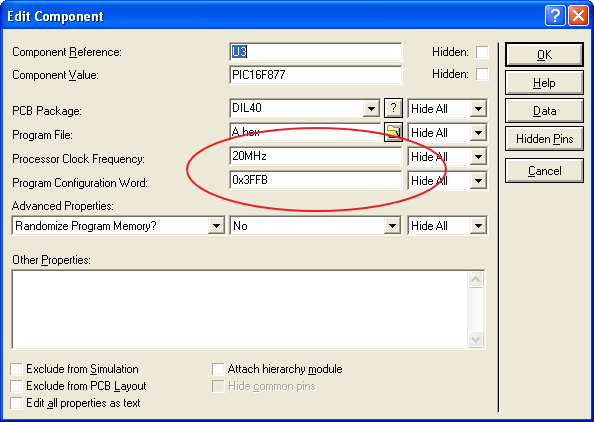
One issue is the failure to set the PIC clock frequency in the device properties, it is currently set at 20MHz it appears you may have intended it to be 4MHz.
In the case of PIC simulation, the crystal in the schematic plays little to no role in the clock frequency of the simulation.
Another possible issue is the proper configuration of Configuration Register settings, which is accomplished in the MikroC IDE. Many of the MikroC libraries are dependent on properly configuring the clock frequency for the library routines to function properly.
BigDog
- - - Updated - - -
Note: The TX and RX lines are reversed between the MAX232 and the DB9 ComPim, causing a line contention.
Once these lines are switched and the correct clock frequency configured, the simulation appears run without error.
Hi there, I'm having the same contention error on RX. How can I solve this problem. I'm sending AT but can't receive OK respond. Tested on HyperTerminal with AT commands and worked fine.
This is the first time that I'm using PIC16F877. Please warn me if there are any mistakes. I have fixed the circuit by adding some resistors to both sides of MAX232. I don't get any warnings from Proteus now but can't either get any reply from the GSM.
sbit LCD_RS at RC0_bit;                 // LCD_RS assigned to PORT RC0;
sbit LCD_EN at RC1_bit;                 // LCD_EN assigned to PORT RC1;
sbit LCD_D4 at RC2_bit;                 // LCD_D4 assigned to PORT RC2;
sbit LCD_D5 at RC3_bit;                 // LCD_D5 assigned to PORT RC3;
sbit LCD_D6 at RC4_bit;                 // LCD_D6 assigned to PORT RC4;
sbit LCD_D7 at RC5_bit;                 // LCD_D7 assigned to PORT RC5;

sbit LCD_RS_Direction at TRISC0_bit;    // LCD_RS assigned to TRIS C0;
sbit LCD_EN_Direction at TRISC1_bit;    // LCD_EN assigned to TRIS C1;
sbit LCD_D4_Direction at TRISC2_bit;    // LCD_D4 assigned to TRIS C2;
sbit LCD_D5_Direction at TRISC3_bit;    // LCD_D5 assigned to TRIS C3;
sbit LCD_D6_Direction at TRISC4_bit;    // LCD_D6 assigned to TRIS C4;
sbit LCD_D7_Direction at TRISC5_bit;    // LCD_D7 assigned to TRIS C5;

void main(){
     ADCON1 = 0x06; //Analog to Digital Conversion
     TRISA=0xFF;   //Set PORTA as Input
     TRISB=0x00;   //Set PORTB as Output
     TRISC=0x80; //set direction of PORTC6 as output -- TX -- transmitter //set direction of PORTC7 as input -- RX -- reciever
     TRISD =0x00;
     TRISE =0x00;

     UART1_init(9600);  // Initialize UART at 9600bpm
     Lcd_Init();
     Lcd_cmd(_LCD_CLEAR);
     Lcd_cmd(_LCD_CURSOR_OFF);

     UART1_Write_Text("AT");
     delay_ms(1000);
     UART1_Write(0x0D); // ENTER
     delay_ms(2000);
     Lcd_Out(1,1,"OK received");
     delay_ms(500);
     Lcd_cmd(_LCD_CLEAR);
     Lcd_cmd(_LCD_CURSOR_OFF);

     UART1_Write_Text("AT+CMGF=1");
     delay_ms(1000);
     UART1_Write(0x0D); // ENTER
     delay_ms(2000);
     Lcd_Out(1,1,"TEXT Mode On");
     delay_ms(500);
     Lcd_cmd(_LCD_CLEAR);
     Lcd_cmd(_LCD_CURSOR_OFF);

     UART1_Write_Text("AT+CMGS=");   // AT+CMGS=
     delay_ms(1000);
     UART1_Write(0x22);  // "
     delay_ms(2000);
     UART1_Write_Text("+905303680459");   // Phone number
     delay_ms(2000);
     UART1_Write(0x22);    // "
     UART1_Write(0x0D); // ENTER
     delay_ms(2000);
     UART1_Write_Text("AUTOMATION TEST 2!");
     UART1_Write(0x0D);
     delay_ms(2000);
     UART1_Write(26);  // CTRL+Z
     UART1_Write(0x0D);
     Delay_ms(2000);
     Lcd_Out(1,1, "Message Sent");
     delay_ms(3000);

     Lcd_cmd(_LCD_CLEAR);
     Lcd_cmd(_LCD_CURSOR_OFF);
}
This site uses cookies to help personalise content, tailor your experience and to keep you logged in if you register.
By continuing to use this site, you are consenting to our use of cookies.