kookooli
Junior Member level 3

- Joined
- Jul 10, 2014
- Messages
- 30
- Helped
- 0
- Reputation
- 0
- Reaction score
- 0
- Trophy points
- 6
- Activity points
- 235
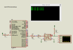
Hi,
I'm trying to send serial data from one micro to another mirco via optocoupler.
my sending speed is 9600bit/sec.
i'm using H11L1 optocoupler.it's speed is 1Mhz(from datasheet)..
but it doesnt work .
Can anyone help me ?
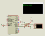
I'm trying to send serial data from one micro to another mirco via optocoupler.
my sending speed is 9600bit/sec.
i'm using H11L1 optocoupler.it's speed is 1Mhz(from datasheet)..
but it doesnt work .
Can anyone help me ?