Continue to Site

Welcome to EDAboard.com

Welcome to our site! EDAboard.com is an international Electronics Discussion Forum focused on EDA software, circuits, schematics, books, theory, papers, asic, pld, 8051, DSP, Network, RF, Analog Design, PCB, Service Manuals... and a whole lot more! To participate you need to register. Registration is free. Click here to register now.

Select FET for VCR application

Status
Not open for further replies.

Al J

Newbie level 5
Joined
Jul 28, 2011
Messages
9
Helped
0
Reputation
0
Reaction score
0
Trophy points
1,281
Activity points
1,360
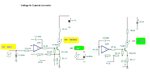
I am new to the world of FETs and need some help in choosing one. It will be used to make a voltage controlled resister (I hope) in an automotive application.

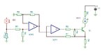
Range of VCR's resistance desired: 5-70 ohms
Vcc: 12v
Input circuit is thermistor(?) whose operation range is 250-2k ohms. Expect to use Vcc on a voltage divider to provide control voltage to VCR.
 

For this application I think you need also to specify the maximum current drawn by the FET.
 

6.6 ohms: 189 mA @ 1.25 V
68 ohms: 96 mA @ 6.3 V

We have a mismatch between the meter in the dash of a project car and the sensor on the block. Looking to see if an VCR is a suitable solution. Meter wants to see 6-68 ohms, sensor range is 45-1k ohms.

Meter operates on 7v mechanically regulated "dc" (couple of hz pulse), so that is they type of signal that would be looking at the VCRs resistance. Annoying, but I don't think it should matter.
 

This type of application require to use a voltage to current converter.
Something like this:
 

Attachments

  • demo 1.JPG
    demo 1.JPG
    27.7 KB · Views: 57

hummm...
PTC by the thermistor? Positive Temp. Coefficient?
AM1 just an ammeter (to be replaced by load)?
Vertical bar inside the opamp symble... never seen that before.. what does that mean?
 

:-D
C’mon, forget about small additional details in the attached diagram like NTC/PTC/OA , this schematics was just the starting point, the whole idea remain: use a ‘’voltage to current converter’’.
 

okay. Working through the 2nd stage of the circuite. Starting to think I am going to have to go up in the attic and get my copy of opamp-cookbook. It has been way to long.... but I really am supposd to be able to work this out from the idealized opamp rules... embarrassing. :)

---------- Post added at 16:33 ---------- Previous post was at 16:07 ----------

Ahhhh, NS app note 31!
 

Let’s consider
NTC = 47-50 ohms > I out= adjustable from 95-100mA
NTC = 1000 ohms I out = adjustable from 190-200mA.
Is that correct ?
 

Attachments

  • VC converter.JPG
    VC converter.JPG
    74.6 KB · Views: 40

NTC the sensor that the meter expects to see
PTC is what we have in the engine.

NTC = 6(hot) to 70(cold) ohms ->
I out= adjustable from 190mA (hot) to 95mA (cold)

PTC = 40(hot) to 1000(cold) ohms I ->
out = adjustable from ??-??mA.

Sorry, not sure about the ??-??... depends on what we choose to power this part of the circuit with. We got +12, 7pdc, and probably 1 or 2 voltages needed to power the op amp. Sorry if I am being dumb. Actually I don’t think the 7pdc is available as loading it further would probably screw up the other meter (fuel) that uses this as its supply.
 

OK, perfect, in this case need to find the internal resistance of the meter.

Rm1 + Rptc1 = 7V/190mA > Rm1 = 30.84 ohms

I assume the second measured value for the thermistor was wrong. (maybe compared with the testing situation in the normal operation thermistor heated also by the current flow thru the circuit).
Rm2 + Rptc2 = 7V/95mA > Rm2 = 3.7 ohms.(!)
So let’s assume the internal resistance is about 30-32 ohms.
Previous schematics need to be changed.
 

Not clear which one you are referring to (2nd value). I do not have the NTC sensor. The 6 and 70 ohm values I got by placing resistors in the place of the sensor and seeing where the meter red... "cold" and "hot" are simply where the pointer pointed... and these (it seemed to me) are what the meter wanted to see. I ran these values twice (I had mislaid the paper where the first number were written.)

As for the numbers for PTC I got these from the sensor on the car... ran values from freezing (in freezer) to boiling (stove/water)... 45 was at 210 degrees, 793 was at 72 room temp, 4.6k was at freezing.

Now to figure out what you were calc. :)

---------- Post added at 20:42 ---------- Previous post was at 20:25 ----------

w/ simulated NTC thermistor(?):
6.6 ohms * 189 mA is aprox 1.24 v
68 ohms * 96 mA is aprox 6.3 v
so ohms law agrees with my measurements (all 6 numbers were measured).

The meter is the bimatal/nichrome wire type. Maybe that explains the anom.

---------- Post added at 20:49 ---------- Previous post was at 20:42 ----------

hummm... .01 ohm and -2.38 ohm. I see your point. We are doing this stuff like the V are DC, and they are not. Problem coming in from there?
 

We need to consider the meter use 190-195 mA at full scale and 95-100mA at minimum. A possible diagram:
 

Attachments

  • NTC Meter v2.JPG
    NTC Meter v2.JPG
    62.9 KB · Views: 46

Good lord you did some work. Will start studying it.
 

Some details about schematics:
1. Current source ~ 2mA in order to obtain for NTC=50 ohms ~ 100mV and for NTC=1k ~ 2V
2. Differential Amplifier to add the values in order to obtain for 50 ohms ~900mV and for 1K down to ~450 mV
3. Voltage to current converter (at minimum 450mV to obtain ~95mA and for maximum 900mV to obtain ~190mA)

............


So now the first error detected, R13= 680 ohms (not 270 ohms)


Attachments

  • VC3.JPG
    VC3.JPG
    30.6 KB · Views: 51
  • VC2.JPG
    VC2.JPG
    44.5 KB · Views: 52
  • VC1.JPG
    VC1.JPG
    41.6 KB · Views: 48
Last edited:

Status
Not open for further replies.

Part and Inventory Search

Welcome to EDABoard.com

Sponsor

Back
Top