Continue to Site

Welcome to EDAboard.com

Welcome to our site! EDAboard.com is an international Electronics Discussion Forum focused on EDA software, circuits, schematics, books, theory, papers, asic, pld, 8051, DSP, Network, RF, Analog Design, PCB, Service Manuals... and a whole lot more! To participate you need to register. Registration is free. Click here to register now.

[ARM] Seeing UART data in Oscilloscope

Status
Not open for further replies.

vikky

Full Member level 3
Joined
Oct 18, 2007
Messages
150
Helped
4
Reputation
8
Reaction score
3
Trophy points
1,298
Activity points
2,664
Hi,

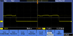
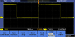
Can anyone please advice how to measure data going out of my Tx pin in microcontroller with the help of a oscilloscope.I am getting junk value at the terminal.My max 232 circuit is working fine.I want to check whether things are fine in my microcontroller side.

Thanks.
 

hi vikky,
The usual causes of corrupt RS232 data are in the Baud rate settings not being the same or the Parity Bit ie: Even or Odd or Off.

On your scope you should see for each character, a 10 bit long string, 1 Start bit, 8 data bits and 1 Stop bit.

On the PIC pin its a TTL level and the output of the MAX232 +/-9V level.

If you can sync your scope on the start bit by sending a test character every 10mSec, you should be able to see the data bits. Measure the trace time from the Start to Stop bits this will give you an indication of the Baud rate.

A 9600 baud character is 10 bits [ or 960 char/sec] so thats 1/960 mSec

E
 
  • Like
Reactions: vikky

    vikky

    Points: 2
    Helpful Answer Positive Rating
if you look at
https://en.wikipedia.org/wiki/RS-232

it shows an oscilloscope image of the character K - ASCII code 0x4B

looking at it in more detail one can measure the baud rate, e.g. looking at TTL signal of K
Dscn0622.jpg

zooming in and measuring the width of one bit
Dscn0615.jpg
the cursors read 312 and 208 microseconds which gives a width of 104 microseconds which gives a baud rate of 9615 - the actual baudrate is 9600
 
  • Like
Reactions: vikky

    vikky

    Points: 2
    Helpful Answer Positive Rating
Hello!

Everyone has his own tricks. When I didn't have a modern scope (with serial readout),
I used to send sequences like 0xAA (10101010) and 0x55 (01010101). This helps to spot
everything instantly, and half a period is the place taken by one bit.

Dora.
 
  • Like
Reactions: vikky

    vikky

    Points: 2
    Helpful Answer Positive Rating
Thanks esp1,horace1,doraemon for your replies.

I am adding an image which i am getting while sending K.The hex value i am getting by sending K is 0XFD.Is it problem with baud rate synchronization or any problem with the circuit.MAX 232b circuit is fine since i wired together 11 and 12 and i was able to get the echo in my terminal.

Yeah dora thats a good idea.
 

Attachments

  • K.PNG
    K.PNG
    6 KB · Views: 227

if you are receiving rubbish the probable cause it the baud rate of the transmitter and the receiver are different
what do you think the baud rate from the microcontroller is?
could you post the code?
 

if you are receiving rubbish the probable cause it the baud rate of the transmitter and the receiver are different
what do you think the baud rate from the microcontroller is?
could you post the code?
The baud rate is 9600.
I am posting the UART portion of the code


Code C - [expand]
1
2
3
4
5
6
7
8
9
10
11
12
13
14
15
16
17
18
19
20
21
22
23
24
25
26
27
28
29
30
31
32
33
34
35
36
37
38
39
40
41
42
43
44
45
46
47
48
49
50
51
52
53
54
55
56
57
58
59
60
61
62
63
64
65
66
67
68
69
70
71
72
73
74
75
76
77
78
79
80
81
82
83
84
85
86
87
88
89
90
91
92
93
94
95
96
97
98
99
100
101
102
103
104
105
106
107
108
109
110
111
112
113
114
115
116
117
118
119
120
121
122
123
124
125
126
127
128
129
130
131
132
133
134
135
136
137
138
139
140
141
142
143
144
145
146
147
148
149
150
151
152
153
154
155
156
157
158
void UARTSend(uint32_t portNum, uint8_t *BufferPtr, uint32_t Length)
{
 
  while ( Length != 0 )
  {
    if ( portNum == 0 )
    {
      /* THRE status, contain valid data */
#if !TX_INTERRUPT
      while ( !(LPC_UART0->LSR & LSR_THRE) );
      LPC_UART0->THR = *BufferPtr;
#else
      /* Below flag is set inside the interrupt handler when THRE occurs. */
      while ( !(UARTTxEmpty0 & 0x01) );
      LPC_UART0->THR = *BufferPtr;
      UARTTxEmpty0 = 0; /* not empty in the THR until it shifts out */
#endif
    }
    else
    {
      /* THRE status, contain valid data */
#if !TX_INTERRUPT
      while ( !(LPC_UART1->LSR & LSR_THRE) );
      LPC_UART1->THR = *BufferPtr;
#else
      /* Below flag is set inside the interrupt handler when THRE occurs. */
      while ( !(UARTTxEmpty1 & 0x01) );
      LPC_UART1->THR = *BufferPtr;
      UARTTxEmpty1 = 0; /* not empty in the THR until it shifts out */
#endif
    }
    BufferPtr++;
    Length--;
  }
  return;
}
 
void UARTInit(uint32_t portNum, uint32_t baudrate)
{
  uint32_t i, Fdiv;
  uint32_t regVal;
 
  if ( portNum == 0 )
  {
    UARTTxEmpty0 = 1;
    UARTCount0 = 0;
    for ( i = 0; i < BUFFSIZE; i++ )
    {
      UARTBuffer0[i] = 0;
    }
    NVIC_DisableIRQ(UART0_IRQn);
 
    SetupUART_Location( portNum, 0 );   /* default is location 0 */
 
    /* Enable UART 0 clock */
    LPC_SYSCON->PRESETCTRL |= (0x1<<2);
    LPC_SYSCON->SYSAHBCLKCTRL |= (0x1<<12);
    LPC_SYSCON->UART0CLKDIV = 0x1;     /* divided by 1 */
 
    LPC_UART0->LCR = 0x83;             /* 8 bits, no Parity, 1 Stop bit */
    regVal = LPC_SYSCON->UART0CLKDIV;
    Fdiv = ((SystemCoreClock/regVal)/16)/baudrate ; /*baud rate */ 
 
    
    LPC_UART0->DLM = 0x00;
    
    LPC_UART0->DLL = 0x13;
 
 
    LPC_UART0->LCR = 0x03;      /* DLAB = 0 */
    LPC_UART0->FDR = 0x10;      /* set to default value: 0x10 *///0x10
    LPC_UART0->FCR = 0x07;      /* Enable and reset TX and RX FIFO. */
 
    /* Read to clear the line status. */
    regVal = LPC_UART0->LSR;
 
    /* Ensure a clean start, no data in either TX or RX FIFO. */
    while ( (LPC_UART0->LSR & (LSR_THRE|LSR_TEMT)) != (LSR_THRE|LSR_TEMT) );
    while ( LPC_UART0->LSR & LSR_RDR )
    {
      regVal = LPC_UART0->RBR;  /* Dump data from RX FIFO */
    }
 
    /* Enable the UART Interrupt */
    NVIC_EnableIRQ(UART0_IRQn);
 
#if TX_INTERRUPT
    LPC_UART0->IER = IER_RBR | IER_THRE | IER_RLS;  /* Enable UART interrupt */
#else
    LPC_UART0->IER = IER_RBR | IER_RLS; /* Enable UART interrupt */
#endif
  }
  else
  {
    UARTTxEmpty1 = 1;
    UARTCount1 = 0;
    for ( i = 0; i < BUFFSIZE; i++ )
    {
      UARTBuffer1[i] = 0;
    }
    NVIC_DisableIRQ(UART1_IRQn);
 
    SetupUART_Location( portNum, 0 );   /* default is location 0 */
 
    /* Enable UART 1 clock */
    LPC_SYSCON->PRESETCTRL |= (0x1<<3);
    LPC_SYSCON->SYSAHBCLKCTRL |= (0x1<<13);
    LPC_SYSCON->UART1CLKDIV = 0x1;     /* divided by 1 */
 
    LPC_UART1->LCR = 0x83;             /* 8 bits, no Parity, 1 Stop bit */
    regVal = LPC_SYSCON->UART1CLKDIV;
    Fdiv = ((SystemCoreClock/regVal)/12)/baudrate ; /*baud rate */
 
    //LPC_UART1->DLM = Fdiv / 256;
    //LPC_UART1->DLL = Fdiv % 256;
    LPC_UART0->DLM = 0x00;
        //LPC_UART0->DLL = Fdiv % 256;
        LPC_UART0->DLL = 0x13;
    LPC_UART1->LCR = 0x03;      /* DLAB = 0 */
    LPC_UART1->FDR = 0x10;      /* set to default value: 0x10 */
    LPC_UART1->FCR = 0x07;      /* Enable and reset TX and RX FIFO. */
 
    /* Read to clear the line status. */
    regVal = LPC_UART1->LSR;
 
    /* Ensure a clean start, no data in either TX or RX FIFO. */
    while ( (LPC_UART1->LSR & (LSR_THRE|LSR_TEMT)) != (LSR_THRE|LSR_TEMT) );
    while ( LPC_UART1->LSR & LSR_RDR )
    {
      regVal = LPC_UART1->RBR;  /* Dump data from RX FIFO */
    }
 
    /* Enable the UART Interrupt */
    NVIC_EnableIRQ(UART1_IRQn);
 
#if TX_INTERRUPT
    LPC_UART1->IER = IER_RBR | IER_THRE | IER_RLS;  /* Enable UART interrupt */
#else
    LPC_UART1->IER = IER_RBR | IER_RLS; /* Enable UART interrupt */
#endif
  }
  return;
}
 
int main (void)
    {
 
 SetupUART_Location(0,0);
    UARTInit(0,9600);
while(1)
    {
 
         LPC_UART0->IER = IER_THRE | IER_RLS;
 
         UARTSend( 0, "K" , 1);
        LPC_UART0->IER = IER_THRE | IER_RLS |                 IER_RBR;
}
}


The program had worked fine before.now it is misbehaving.I am using a external MAX 232 circuit with different power supply.I have made the ground common.Is the problem in circuit or firmware?In circuit i just take the Tx and Rx pins out and give it to a external max232 circuit which works fine.
 
Last edited by a moderator:

Please check the waveform i am receiving now.But the junk data refuses to go away.
 

Attachments

  • TEK00001.PNG
    TEK00001.PNG
    5.8 KB · Views: 508

are the pulses a sigle bit ?
if each division is 4microseconds each pulse is 12microseconds giving a baud rate of 83333 baud?
a very unusual value!
can you show us the whole character rather than a couple of bits?
also the circuit you are using?
 

i am attaching the circuit i am using.the normal max circuit.does the baud rate has anything to do with the circuit?i guess MAX 232 circuit is fine since i wired together 11 and 12 and i was able to get the echo in my terminal.meanwhile i will try to get you the whole character.
 

Attachments

  • serial circuit.bmp
    272.4 KB · Views: 128

the MAX232 converts the TTL signal from the processor to RS232 and does not effect baud rate
it can corrupt the signal if not wired correctly - you can check by looking at the TTL signal and then the RS232 signal

you circuit looks OK - this is one I used on a PIC24FJ256GB110
MAX232.jpg

the baud rate is determined by factors such as the microprocessor perheripal clock (derived from the crystal clock), UART drivisors and baudrate counters, etc
have a look at this post
https://www.edaboard.com/threads/320099/
 
Last edited:

Hi,

in your circuit: did you notice the wrong polarity of C6?

Klaus
 
  • Like
Reactions: vikky

    vikky

    Points: 2
    Helpful Answer Positive Rating
I see that you C6 appears to be the wrong way around
also you are using 10microFarad rather the recommended 1microFarad

from TI max232 documentation
www.ti.com/lit/ds/symlink/max232.pdf

their application circuit is
MAX232a.jpg

I note that the documentation says 0.1microFarad are OK which our circuit uses

these days we don't use MAX232 and RS232 unless we have to
we use FTDI USB-TTL serial cables or similar
https://www.ftdichip.com/Products/Cables/USBTTLSerial.htm

it saves space on the PCB and very few laptops have RS232 COM ports anymore
 
  • Like
Reactions: vikky

    vikky

    Points: 2
    Helpful Answer Positive Rating
Now i used MAX3232 which required 3.3V instead of MAX232.The problem was the microcontroller board has both 3.3V and 5V and 5V was having loading effect when i connected MAX 232 circuit with MAX IC sitting on it.Microcontroller works on 3.3V and it was working fine.So i connected a circuit which had MAX3232 which needs only 3.3V and its working fine now.
Thanks everyone for your help and thanks horace1 for your time and help.
 

Status
Not open for further replies.

Similar threads

Part and Inventory Search

Welcome to EDABoard.com

Sponsor

Back
Top