Hassan Munir
Newbie level 6
Hi,
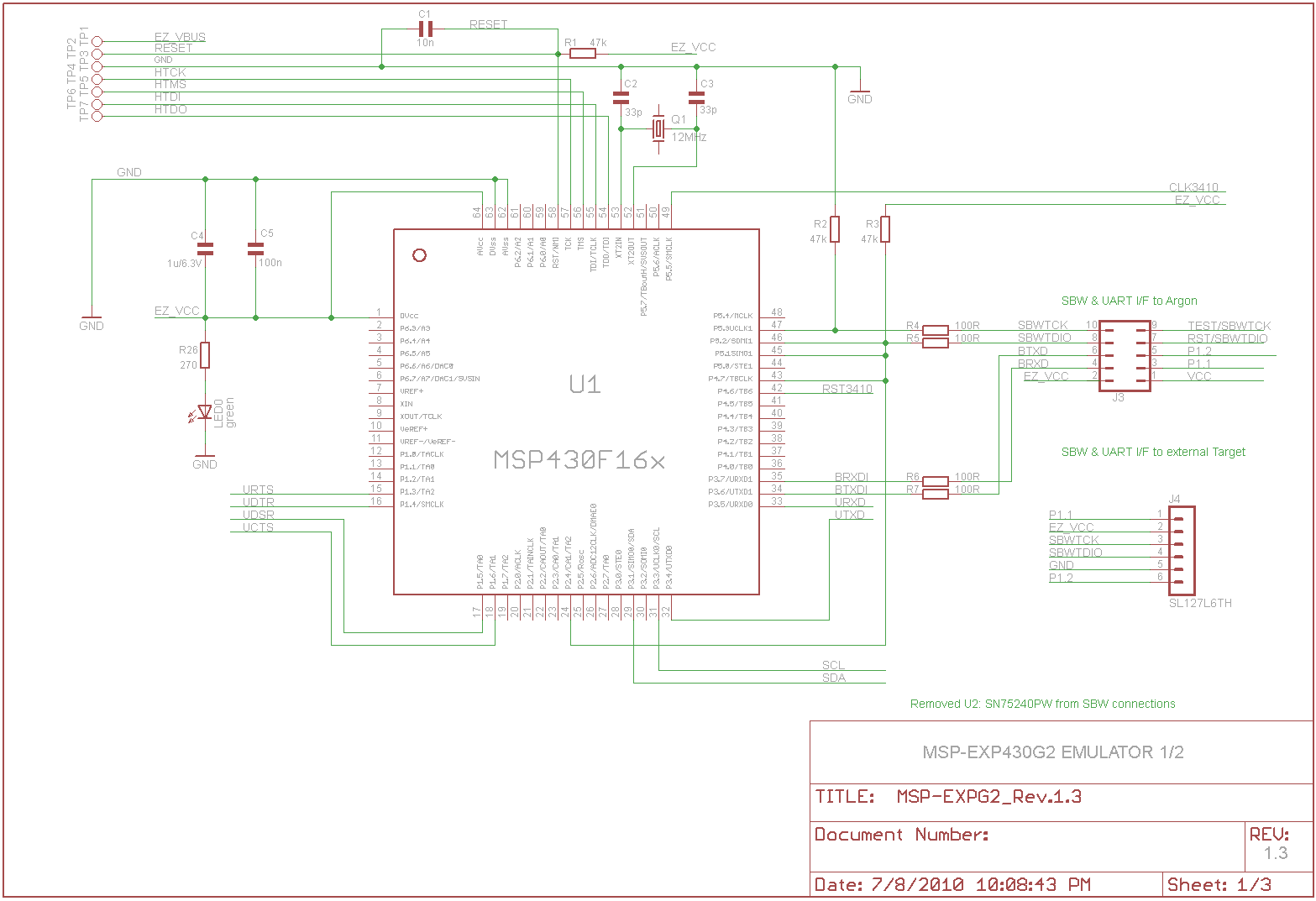
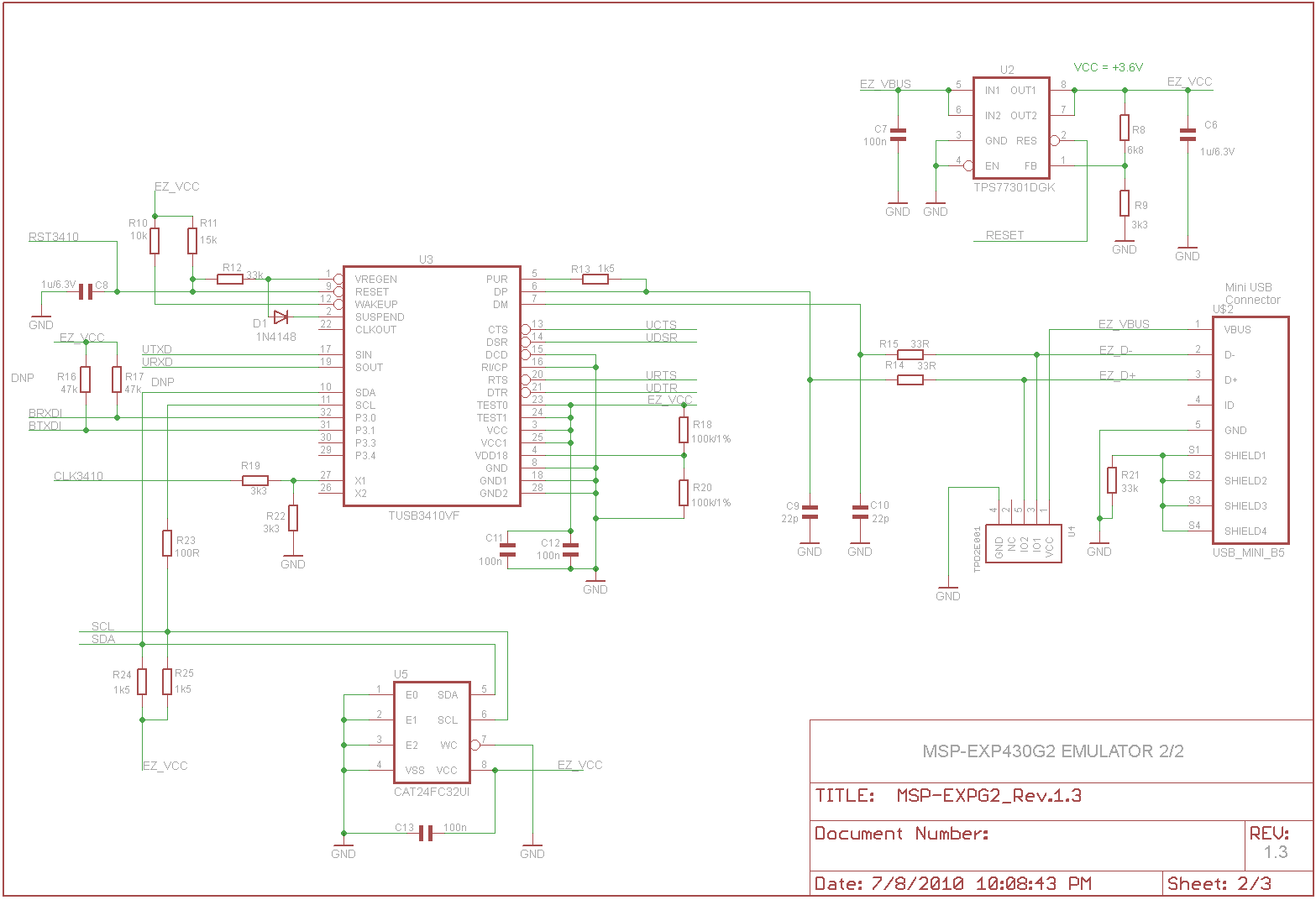
I want to increase my skills on schematic capture board design. Most books I read are focused on integrated circuits. However, instead of knowing what is happening inside the IC's I want to know once ICs are bought, how to connect them using circuitry as necessary as seen in schematic below. What are some
ways I can learn this type of circuit design and not IC design. I have some idea about it such as the fact that capacitors are used in power supply to avoid ripple/ ringing of the power supply , so that smooth DC voltage will enter the IC , however how do I know what value of capacitor to use. Typical schematics have 100nF, .1 uF, 1uF, 10 uF, but I wan't to understand why. I want understand not just about the capacitor use but the overall interfacing such as the one shown in the schematic below. Please Help