Continue to Site

Welcome to EDAboard.com

Welcome to our site! EDAboard.com is an international Electronics Discussion Forum focused on EDA software, circuits, schematics, books, theory, papers, asic, pld, 8051, DSP, Network, RF, Analog Design, PCB, Service Manuals... and a whole lot more! To participate you need to register. Registration is free. Click here to register now.

Scan Chain Test component VHDL

Status
Not open for further replies.

Andrea Scafuto

Newbie level 4
Newbie level 4
Joined
Nov 2, 2013
Messages
7
Helped
0
Reputation
0
Reaction score
0
Trophy points
1
Visit site
Activity points
63
Hello gurus, i'm new at VHDL programming, i have to create a Scan Chain from scratch, and starting from this one i have to test a Component.
I created first of all flip-mux, a component that combine a D-latch flip flop and 2-1 Multipliplexer.
My scanchain is composed by 4 flip-mux, when Scan_en is disabled, the scan chain output is the input Din0, Din1,Din2, Din3.
I implemented my scanchain, I need to create the "Component".
I was thinking a simple 1 bit adder, for example:

if the output string is -> 0 0 1 0

after the string goes into the Component the exit will be -> 0 0 1 1

To implement this i've created a new vhdl module that has 4 input and 4 output, now how i can handle the scope of my scanchain variables, to implement my component?
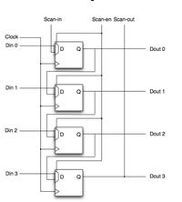
 

You will also need clock, scan-in inputs and scanen and scan out outputs. So thats 6 inputs 6 outputs total.
 

Hi TrickyDicky, first of all, thanks for the answer, i'll try to post my code, so i can explain the problem :


Code VHDL - [expand]
1
2
3
4
5
6
7
8
9
10
11
12
13
14
15
16
17
18
19
20
21
22
23
24
25
26
27
entity Sommatore is
    Port ( In0 : in  STD_LOGIC;
           In1 : in  STD_LOGIC;
           In2 : in  STD_LOGIC;
           In3 : in  STD_LOGIC;
           O0 : out  STD_LOGIC;
           O1 : out  STD_LOGIC;
           O2 : out  STD_LOGIC;
           O3 : out  STD_LOGIC);
end Sommatore;
 
architecture Behavioral of Sommatore is
 
component boundscan is
Port    (   Din0 : in  STD_LOGIC;
           Din1 : in  STD_LOGIC;
           Din2 : in  STD_LOGIC;
           Din3 : in  STD_LOGIC;
           Scan_en : in  STD_LOGIC;
           Scan_in : in  STD_LOGIC;
           clk : in  STD_LOGIC;
           Dout0 : out  STD_LOGIC;
           Dout1 : out  STD_LOGIC;
           Dout2 : out  STD_LOGIC;
           Dout3 : out  STD_LOGIC;
           Scan_out : out  STD_LOGIC);
end component;


--------------------------------------------------------------
Now, my Dout0, Dout1, Dout2, Dout3 will be In0,In1,In2,In3.
After the circuit elaboration i'll have in output Oo, O1, O2, O3.
Followin the example in the first post :

Scan_en: 0 (Disabled)

Code:
Din0 = 0 ---> Dout0 = 0
Din1 = 0 ---> Dout1 = 0
Din2 = 1 ---> Dout2 = 1
Din3 = 0 ---> Dout3 = 0

When they go in Component "Sommatore"

Code:
Dout0 ---> In0 = 0
Dout1 ---> In1 = 0
Dout2 ---> In2 = 1 
Dout3 ---> In3 = 0

In output to sommatore i have to find

Code:
O0 = 0
O1 = 0
O2 = 1
O3 = 1

The problem is when i realize the logic of the component i have visibility problem, the simulator says that : Undefined symbol 'Dout0'
 
Last edited by a moderator:

You didn't show the architecture body and the entity is still missing the said control signals.
 

You didn't show the architecture body and the entity is still missing the said control signals.


You're right, sorry for the missing:


Code:
begin

In0 <= Dout0;
In1 <= Dout1;
In2 <= Dout2;
In3 <= Dout3;


O0 <= In0;
O1 <= In1;
O2 <= In2;
O3 <= In3 OR '1';


end Behavioral;
 
Last edited by a moderator:

I suppose that's not the correct architecture body, can't imagine that your synthesis tool or simulator accepts it.

Referring to the original post, I don't see the said one bit "flip-mux" component, nor respective component instantiation statements.
I guess you better to start reading a VHDL text book.
 

Hi FvM, I have flipmux in other files that i recalled as a component, if u want i can zip you all file, anyway the flipmux component code is :


Code VHDL - [expand]
1
2
3
4
5
6
7
8
9
10
11
12
13
14
15
16
17
18
19
20
21
22
23
24
25
26
27
28
29
30
31
32
33
34
35
36
37
38
39
40
41
42
43
44
45
46
47
48
49
50
library IEEE;
use IEEE.STD_LOGIC_1164.ALL;
 
-- Uncomment the following library declaration if using
-- arithmetic functions with Signed or Unsigned values
--use IEEE.NUMERIC_STD.ALL;
 
-- Uncomment the following library declaration if instantiating
-- any Xilinx primitives in this code.
--library UNISIM;
--use UNISIM.VComponents.all;
 
entity fm is
    Port ( Din : in  STD_LOGIC;
           Scan_in : in  STD_LOGIC;
           Scan_en : in  STD_LOGIC;
           clk : in  STD_LOGIC;
           Dout : out  STD_LOGIC);
end fm;
 
 
architecture Structural of fm is
 
--Definizione del Componente Flip-Flop
-------------------------------------
component flip_flop is
    Port ( d : in  STD_LOGIC;
          clock : in  STD_LOGIC;
          q : out  STD_LOGIC);
end component;
-------------------------------------
 
--Definizione del Componente Mux2-1
-------------------------------------
component mux2_1 is 
    Port ( a : in  STD_LOGIC;
          b : in  STD_LOGIC;
          sel : in  STD_LOGIC;
          o : out  STD_LOGIC);
end component;
-------------------------------------
signal temp : STD_LOGIC;
 
begin
--Port Map dei componenti
 
mux : mux2_1 port map(Din, Scan_in, Scan_en, temp); 
ff : flip_flop port map(temp, clk, Dout);   
 
end Structural;


O.K., looks good. But component fm doesn't appear in the previously shown code. Neither instances of component fm nor component boundscan.


I would strongly suggest to use named instead of positional association in component instances. Makes the code better readable and avoids nasty confusion of ports.

Ok thanks for the advice, anyway i have a problem in Component Sommatore when i try to call variables defined in other components.
 

i have a problem in Component Sommatore when i try to call variables defined in other components
You don't "call variables" in structural VHDL design, just connect components. As said, it can't be seen how you did it.

It's done right in entity fm, I would expect similar component instantiations in the entity Sommatore.
 

You don't "call variables" in structural VHDL design, just connect components. As said, it can't be seen how you did it.

It's done right in entity fm, I would expect similar component instantiations in the entity Sommatore.

Ok, I do the same for Sommatore but, when i make signal matching :


[Syntax =vhdl]
In0 <= Dout0;
In1 <= Dout1;
In2 <= Dout2;
In3 <= Dout3;

O0 <= In0;
O1 <= In1;
O2 <= In2;
O3 <= In3 OR '1';
[syntax]

The simulator gives me error: "Undefined symbol 'Dout0' ";
why?
 

You are repeating the code snippet you posted before. It still doesn't seem make sense to me. Post the complete architecture with signal definitions and component instantiations.
 

We can refer to the entity boundscan which essentially contains the required design.
The outputs u0 to u3 of the fm component instances are now unconnected.
Code:
library IEEE;
use IEEE.STD_LOGIC_1164.ALL;

entity boundscan is
    Port ( Din0 : in  STD_LOGIC;
           Din1 : in  STD_LOGIC;
           Din2 : in  STD_LOGIC;
           Din3 : in  STD_LOGIC;
           Scan_en : in  STD_LOGIC;
           Scan_in : in  STD_LOGIC;
           clk : in  STD_LOGIC;
           Dout0 : out  STD_LOGIC;
           Dout1 : out  STD_LOGIC;
           Dout2 : out  STD_LOGIC;
           Dout3 : out  STD_LOGIC;
           Scan_out : out  STD_LOGIC);
end boundscan;

architecture Structural of boundscan is

component fm is
Port    (  Din : in  STD_LOGIC;
           Scan_in : in  STD_LOGIC;
           Scan_en : in  STD_LOGIC;
           clk : in  STD_LOGIC;
           Dout : out  STD_LOGIC);
end component;

signal u0,u1,u2,u3 : STD_LOGIC;

begin

flimux1 : fm Port Map(Din0,Scan_in,Scan_en,clk,u0);
flimux2 : fm Port Map(Din1,u0,Scan_en,clk,u1);
flimux3 : fm Port Map(Din2,u1,Scan_en,clk,u2);
flimux4 : fm Port Map(Din3,u2,Scan_en,clk,u3);

logica : process(Din0,Din1,Din2,Din3,Scan_in,clk,Scan_en)

begin
   
   if Scan_en='0'
   then
          Dout0 <= Din0;
          Dout1 <= Din1;
          Dout2 <= Din2;
          Dout3 <= Din3;
         else
         Scan_out <= Din0;
         
   end if;

end process;

end Structural;

It can be corrected this way:

completely delete the process, all required logic is already in the component instances.

assign the outputs in concurrent code
Code:
dout0 <= u0; 
dout1 <= u1; 
dout2 <= u2; 
dout3 <= u3;
Scan_out <= u3;
 

Status
Not open for further replies.

Similar threads

Part and Inventory Search

Welcome to EDABoard.com

Sponsor

Back
Top