Continue to Site

Welcome to EDAboard.com

Welcome to our site! EDAboard.com is an international Electronics Discussion Forum focused on EDA software, circuits, schematics, books, theory, papers, asic, pld, 8051, DSP, Network, RF, Analog Design, PCB, Service Manuals... and a whole lot more! To participate you need to register. Registration is free. Click here to register now.

sams reading problem in pic16f877a with sim900a

Status
Not open for further replies.

blwin thakur

Newbie level 2
Newbie level 2
Joined
Dec 5, 2013
Messages
2
Helped
0
Reputation
0
Reaction score
0
Trophy points
1
Visit site
Activity points
19
i working on a problem to control devices with sms. i have interfaced sim900a and lcd 16x2 with PIC16f877A. i m able to send sms from sim900a to mobile . but i have problem in reading sms from sim900a and display it on LCD 16x2.i connected my C with SIM900a directly without any chip conversion check out my module .i have checked my programming code and and GSM module by hyperterminal both are working good but i dont know where is the problem .can anyone give me solution?
 

unable to read sms from sim900a

hello guys i m using pic16f877a with sim900a .and i successfully send sms .But i m facing problem in reading sms from sim900a can anybody give me solution that what can be the reason behind the problem
 

Hi as you said you are successful in sending SMS from GSM module can you please share the schematic hardware connection you did for sending SMS from microcontroller
Please share as soon as possible.
Thanks
 

without code and schematic how can we help...

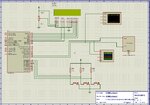
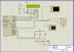
Thanks for the replay, here am attaching schematic of wt am doing with hardware which is not working(not sending SMS).
please help me out. whats wrong in my connections.
am also attaching picture of GSM module am using.
kindly guide.


Code C - [expand]
1
2
3
4
5
6
7
8
9
10
11
12
13
14
15
16
17
18
19
20
21
22
23
24
25
26
27
28
29
30
31
32
33
34
35
36
37
38
39
40
41
42
43
44
45
46
47
48
49
50
51
52
53
54
55
56
57
58
59
60
61
62
63
64
65
66
67
68
69
70
71
72
73
74
75
76
77
78
79
80
81
82
83
84
85
// LCD module connections
sbit LCD_RS at RB4_bit;
sbit LCD_EN at RB5_bit;
sbit LCD_D4 at RB0_bit;
sbit LCD_D5 at RB1_bit;
sbit LCD_D6 at RB2_bit;
sbit LCD_D7 at RB3_bit;
 
sbit LCD_RS_Direction at TRISB4_bit;
sbit LCD_EN_Direction at TRISB5_bit;
sbit LCD_D4_Direction at TRISB0_bit;
sbit LCD_D5_Direction at TRISB1_bit;
sbit LCD_D6_Direction at TRISB2_bit;
sbit LCD_D7_Direction at TRISB3_bit;
// End LCD module connections
 
char txt1[]       = "Calling...";
char txt2[]       = "Msg Sent";
char txt3[]       = "Imran Sayeed";
char txt4[]       = "XYID Technologies";
char txt5[]       = "Waiting input...";
char mobile[]     = "+919900000000;";
 
 
void main() { 
  TRISD = 0xFF;
  PORTD = 0x00;
  UART1_Init(9600);
  Delay_ms(1000);
  Lcd_Init();                        // Initialize LCD
 
  Lcd_Cmd(_LCD_CLEAR);               // Clear display
  Lcd_Cmd(_LCD_CURSOR_OFF);          // Cursor off
  Lcd_Out(1,1,txt3);                 // Write text in first row
  Lcd_Out(2,1,txt4);                 // Write text in second row
  Delay_ms(2000);
  Lcd_Cmd(_LCD_CLEAR);               // Clear display
  Lcd_Out(1,1,txt5);


while(1)
{
if(PORTD.F0 == 0)
{
    UART1_Write_Text("AT+CMGS=");
    Delay_ms(1000);
    UART1_Write(0x22);  // "
    Delay_ms(1000);
    UART1_Write_Text("+919900000000");
    delay_ms(2000);
    UART1_Write(0x22);  // ''
    UART1_Write(0x0D);  // CR
    delay_ms(1000);
    UART1_Write_Text("HI");
    Delay_ms(2000);
    UART1_Write(26);     // CNT+Z
    Delay_ms(2000);
    UART1_Write(0x0D);
    Delay_ms(2000);
    Lcd_Cmd(_LCD_CLEAR);
    Lcd_Cmd(_LCD_CURSOR_OFF);
    Lcd_Out(1,1,txt2);
    Delay_ms(2000);
    Lcd_Cmd(_LCD_CLEAR);
}
if(PORTD.F1 == 0)
{
    UART1_Write_Text("ATD");
    delay_ms(500);
    UART1_Write_Text(mobile);
    delay_ms(500);
    UART1_Write(0x0D);
    Lcd_Cmd(_LCD_CLEAR);
    Lcd_Cmd(_LCD_CURSOR_OFF);
    Lcd_Out(1,1,txt1);
    delay_ms(5000);
    UART1_Write_Text("ATH");
    Lcd_Cmd(_LCD_CLEAR);
    UART1_Write(0x0D);
    delay_ms(500);
}
Lcd_Out(1,1,txt5);
}
}


- - - Updated - - -

without code and schematic how can we help...
here are the attachments
 

Attachments

  • GSM.jpg
    GSM.jpg
    376.2 KB · Views: 114
  • DSC_0472.JPG
    DSC_0472.JPG
    1.5 MB · Views: 110
  • DSC_0472.JPG
    DSC_0472.JPG
    1.5 MB · Views: 98
  • GSM.jpg
    GSM.jpg
    376.2 KB · Views: 104
Last edited by a moderator:

i think it is not necessary to send +91.Just give 10 digit mobile number"9900000000".i tested and got the output in real hardware
 
Last edited:

Try this code. If you get "IRP_bit must be set manually to access xyz variable" message in Compiler and also get garbage data on LCD or UART then use CopyConst2Ram() or change to PIC18F device.

Do you interface GSM to PIC UART directly using TTL pins ? If yes, does your GSM has 5V TTL pins ? Have you connected RxD, TxD, GND of GSM to TxD, RxD GND of PIC ?


Code C - [expand]
1
2
3
4
5
6
7
8
9
10
11
12
13
14
15
16
17
18
19
20
21
22
23
24
25
26
27
28
29
30
31
32
33
34
35
36
37
38
39
40
41
42
43
44
45
46
47
48
49
50
51
52
53
54
55
56
57
58
59
60
61
62
63
64
65
66
67
68
69
70
71
72
73
74
75
76
// LCD module connections
sbit LCD_RS at RB4_bit;
sbit LCD_EN at RB5_bit;
sbit LCD_D4 at RB0_bit;
sbit LCD_D5 at RB1_bit;
sbit LCD_D6 at RB2_bit;
sbit LCD_D7 at RB3_bit;
 
sbit LCD_RS_Direction at TRISB4_bit;
sbit LCD_EN_Direction at TRISB5_bit;
sbit LCD_D4_Direction at TRISB0_bit;
sbit LCD_D5_Direction at TRISB1_bit;
sbit LCD_D6_Direction at TRISB2_bit;
sbit LCD_D7_Direction at TRISB3_bit;
// End LCD module connections
 
char txt1[]       = "Calling...";
char txt2[]       = "Msg Sent";
char txt3[]       = "Imran Sayeed";
char txt4[]       = "XYID Technologies";
char txt5[]       = "Waiting input...";
char mobile[]     = "+919900000000;";
 
 
void main() { 
  TRISC = 0x80;
  TRISD = 0xFF;
  PORTD = 0x00;
  Delay_ms(200);
  UART1_Init(9615);
  Delay_ms(200);
 
  Lcd_Init();                        // Initialize LCD 
  Lcd_Cmd(_LCD_CURSOR_OFF);          // Cursor off
  Lcd_Cmd(_LCD_CLEAR);               // Clear display
  Lcd_Out(1,1,txt3);                 // Write text in first row
  Lcd_Out(2,1,txt4);                 // Write text in second row
  Delay_ms(2000);
  Lcd_Cmd(_LCD_CLEAR);               // Clear display
  Lcd_Out(1,1,txt5);


while(1)
{
if(PORTD.F0 == 0)
{
    Delay_ms(30);
    while(PORTD.F0 == 0);
    UART1_Write_Text("AT\r");
    Delay_ms(1000);
    UART1_Write_Text(AT+CMGF=1\r);  // "
    Delay_ms(1000);
    UART1_Write_Text(AT+CMGS="\9000000000\"\r");
    delay_ms(2000);
    UART1_Write_Text("Hi");
    Delay_ms(500);
    UART1_Write(26);     // CNT+Z
    Delay_ms(2000);
    Lcd_Cmd(_LCD_CLEAR);
    Lcd_Out(1,1,txt2);
    Delay_ms(2000);
    Lcd_Cmd(_LCD_CLEAR);
}
if(PORTD.F1 == 0)
{
    Delay_ms(30);
    while(PORTD.F1 == 0);
    UART1_Write_Text("ATD90000000;\r");
    Lcd_Out(1,1,txt1);
    Delay_ms(5000);
    UART1_Write_Text("ATH");    
}
Lcd_Out(1,1,txt5);
}
}

 
Last edited:

Status
Not open for further replies.

Similar threads

Part and Inventory Search

Welcome to EDABoard.com

Sponsor

Back
Top