Continue to Site

Welcome to EDAboard.com

Welcome to our site! EDAboard.com is an international Electronics Discussion Forum focused on EDA software, circuits, schematics, books, theory, papers, asic, pld, 8051, DSP, Network, RF, Analog Design, PCB, Service Manuals... and a whole lot more! To participate you need to register. Registration is free. Click here to register now.

S11 improvement of passive BPF

Status
Not open for further replies.

Man68

Newbie level 6
Joined
Mar 11, 2013
Messages
11
Helped
0
Reputation
0
Reaction score
0
Trophy points
1,281
Activity points
1,365
Hi all,

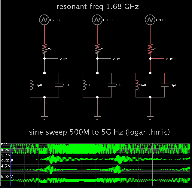
I am designing a 5th order passive BPF (LC) with center frequency of 1.67 GHz and 300 MHz bandwidth. After getting the values for the LC components and simulating in ADS, input/output return losses are quite high (>-10 dB). How can I improve S11 to be at least less than -15 dB?

How I can use the smith chart as the operation frequency BW is too high?!

Thanks
 

In case this helps...

The Q factor is determined by the interaction between:
* neighboring resistance
* coil Henry value
* capacitor value

For a given series resistance, the aim is to use the proper ratio between coil and cap values.

To illustrate:


The coils and caps increase or decrease in multiples of 10. The LC tanks calculate to have an identical center frequency. (1.68 GHz)

The applied sinewave goes from 500 MHz to 5 GHz.

The scope traces show the different responses.

Since you are getting wide bandwidth and too much attenuation, there's a chance your coil value is too low, and your cap value is overly high.

- - - Updated - - -

Maybe your filter is a different configuration. If the above doesn't fit your situation, perhaps you can adapt the concept anyway.
 

Thanks for your reply.

But my filter is a passive L-C network without any resistors and its a 5th order chebyshev filter. Actually my requirement is a wide bandwidth in the pass band and as sharp attenuation as possible in the reject band
 

Real lumped component values will be a problem at this frequency, and the response will look quite a bit different than the simulation. Eliptic type is another choice that may work better.
 

Attachments

  • BPF1670.gif
    BPF1670.gif
    82.5 KB · Views: 52
  • BPF1670_elip.gif
    BPF1670_elip.gif
    68.7 KB · Views: 48

Hi, Thanks for you reply.

My first question is could you please tell how did you design these two filters very quickly?!

And the second is if i do not get the component values in reality, what should I do?
 

This was done using a filter synthesis program to get ballpark values and then ran through an optimizer to get near the desired goals.

The best would be for you to tune the values to try to get the chip inductor values near standard values, because it would be easier to tune a few capacitance values.
If you use air core inductors (that you can stretch and squeeze) it may be better to choose standard capacitor values.

Below I selected standard inductor values, which left capacitor values for tuning. You will have to see which way works the best for you.
You may find this paper interesting. It is a design at a much lower frequency, so you can expect the problems they experienced to be a lot more troublesome at your design frequency. **broken link removed**

You should consider using a distributed type design instead of lumped.
 

Attachments

  • BPF1670_elip_opt.gif
    BPF1670_elip_opt.gif
    70.7 KB · Views: 49
Last edited:

This was done using a filter synthesis program to get ballpark values and then ran through an optimizer to get near the desired goals.

The best would be for you to tune the values to try to get the chip inductor values near standard values, because it would be easier to tune a few capacitance values.
If you use air core inductors (that you can stretch and squeeze) it may be better to choose standard capacitor values.

Below I selected standard inductor values, which left capacitor values for tuning. You will have to see which way works the best for you.
You may find this paper interesting. It is a design at a much lower frequency, so you can expect the problems they experienced to be a lot more troublesome at your design frequency. **broken link removed**

You should consider using a distributed type design instead of lumped.

Could you please tell me what are distributed type?

By the schematic (in simulation) that I have, if the decimal point in the component values are changed, then the total response of the filter is absolutely different! What is the solution?!

- - - Updated - - -

This was done using a filter synthesis program to get ballpark values and then ran through an optimizer to get near the desired goals.

The best would be for you to tune the values to try to get the chip inductor values near standard values, because it would be easier to tune a few capacitance values.
If you use air core inductors (that you can stretch and squeeze) it may be better to choose standard capacitor values.

Below I selected standard inductor values, which left capacitor values for tuning. You will have to see which way works the best for you.
You may find this paper interesting. It is a design at a much lower frequency, so you can expect the problems they experienced to be a lot more troublesome at your design frequency. **broken link removed**

You should consider using a distributed type design instead of lumped.

Could you please tell me what are distributed type?

By the schematic (in simulation) that I have, if the decimal point in the component values are changed, then the total response of the filter is absolutely different! What is the solution?!
 

Status
Not open for further replies.

Similar threads

Part and Inventory Search

Welcome to EDABoard.com

Sponsor

Back
Top