Continue to Site

Welcome to EDAboard.com

Welcome to our site! EDAboard.com is an international Electronics Discussion Forum focused on EDA software, circuits, schematics, books, theory, papers, asic, pld, 8051, DSP, Network, RF, Analog Design, PCB, Service Manuals... and a whole lot more! To participate you need to register. Registration is free. Click here to register now.

Running opamp off voltage divider, a good idea or not?

Status
Not open for further replies.

ants

Full Member level 4
Joined
Feb 20, 2010
Messages
199
Helped
1
Reputation
2
Reaction score
0
Trophy points
1,296
Location
UK
Activity points
3,006
I want to run an opamp, the OPA458, with rails from a voltage divider, is this a good idea?

The setup is this:

Battery 6V : DC-DC booster 12V : Voltage divider +/-6V: OPAMP +/-5V :Transformer +/-5V: Load +/-50V

Also are the values for capacitance and resistance any good? I will use the values in the picture.

Thanks.
 

i think it depends on the DC current drawn by the opamp (and any other components you may have). if very little DC current is drawn (<<1mA) may be it could be a good idea, otherwise the GND node will deviate its idea DC potential.
 

    ants

    Points: 2
    Helpful Answer Positive Rating
For the circuit I'll be using 2 Lithium batteries and drawing 2 amps from them.

How will the positive and negative deviate? For example will the voltages stay at say +6.5V/-5.5V? Or will they change and for example go from +7V/-5V to +8V/-4V?

Thanks.
 

I prefer to correct your explanation in one respect: The OP is "run" from the battery supply, not the voltage divider. The voltage divider is however providing a virtual ground. The problem is, that the OP output current is possibly overloading the virtual ground node. You may want to use a buffered virtual ground to avoid this problem.
 

    ants

    Points: 2
    Helpful Answer Positive Rating
I was going to use a second DC-DC booster that outputted a negative signal to give me the dual supply I need, but decided it would involve too many more components. I did have a look at buffering chips but they didn't look any less complicated than the negative DC booster.

I'm in a quandry now. What is overloading the virtual ground node? If I know what it is I could determine if it would be a problem.

Thanks.
 

Without knowing the circuitry attached to the virtual ground it is impossible to say if the circuit will work. I have made circuits with unbuffered potential dividers for virtual grounds but then I know what is loading them and at what frequencies.

Keith
 

    ants

    Points: 2
    Helpful Answer Positive Rating
The circuit load is a piezo that has a resonant frequency at 100KHz. The opamp is essentially isolated from the load by the transformer, which is 3.2ohms primary. I've diligently followed the datasheet for the DC booster and opamp so I can't see them causing a problem. I've used a similar opamp, transformer and piezo in other combinations so I know they are reliable. I haven't used a DC booster and voltage divider before. The voltage divider is R5, R6, C5 and C6. I'd be grateful for an opinion.

Thanks.
 

I think that the only issue I can see is how much current the opamp will put through the resistive divider due to the load. I assume there will be no DC current so it will just be an AC current. If the dynamic current is large then you will need a large C5/C6 to keep the voltage stable. However, I cannot be sure that there isn't a DC current from the opamp output through the transformer and through the virtual earth. That would pull the virtual earth point.

As you are AC coupling the load with a transformer, why not add a capacitor from the opamp output to the transformer? That would remove any DC currents from the virtual earth.

Keith.
 

    ants

    Points: 2
    Helpful Answer Positive Rating
The 100KHz signal will be a sine wave, it is unlikely to be for example +/-3V and will more likely be +3.2V and -2.8V, there will be no DC offset added by me on the opamp. I was wondering at what level I'd have to put C5 and C6 and was somewhat guessing at 220uF. I could add a capacitor to the opamp output, I'm generally wary of doing that because they usually have a maxium capacitance they will cover without it causing oscillation, however I have just looked at the datasheet and it doesn't say anythiing about capacitive loading, so I think that would be ok.

Regards,

Ant.
 

I sort of assume there must be a DC offset on your opamp. The feedback goes to 0V, not your virtual earth. The non-inverting input comes via the pot VOL which must have a signal which is above ground if it isn't going to clip, unless I am misunderstanding something about the circuit.

You shouldn't have a capacitive loading problem on the opamp output if you put a capacitor in series with the inductor because the capacitance will not be to ground.

It is difficult to know what value of capacitor would be suitable (assuming there isn't a DC problem) without knowing more about the load and transformer. It is the sort of circuit that would be worthwhile simulating assuming you know the characteristics of all the devices.

Keith.

Added after 3 minutes:

By the way, I assume the opamp is the OPA548? You mentioned the OPA458 in your first post (which I cannot find).

Keith.
 

I agree with keith, that connecting a low DC resistance (transformer) most likely doesn't work with a high resistance virtual ground.
 

I have made a mistake and put the opamp feedback to circuit ground rather than virtual ground as I intended, thanks for spotting it!

The signal coming in via the pot VOL is above and below zero volts I've been thinking about whether clipping will occur for a while now and I haven't come up with the answer.

I didn't know that I could put a cap in series with the inductor, would it change the frequency as in an LC circuit?

I have tried simulating piezos in LTspice but the results were unpredictable, I guess I can get the circuit made up and use trial and error to see what cap values to use for the voltage divider.

Thanks for the input.

Added after 10 minutes:

FvM said:
I agree with keith, that connecting a low DC resistance (transformer) most likely doesn't work with a high resistance virtual ground.

I think it probably has something to do with overloading the ground node? Its a concept I haven't got hold of at the moment. Thanks for the reply.

The opamp is the OPA548 not OPA458, after I've written my posts I read them back looking for errors but even so sometimes miss them. Thanks, ant.
 

Attachments

  • opa548_3848.pdf
    1.5 MB · Views: 93

Unless you want to add another resonance, you usually use a large capacitor so any extra resonance is well below where you are working,

A piezo model is similar to a quartz crystal with series and parallel resonances. There are also resonances in other 'modes' e.g. In thickness mode if you are using lateral resonance. You can usually ignore those, but not always.

Keith
 

    ants

    Points: 2
    Helpful Answer Positive Rating
keith1200rs said:
Unless you want to add another resonance, you usually use a large capacitor so any extra resonance is well below where you are working,

Keith

OK, will do.

keith1200rs said:
A piezo model is similar to a quartz crystal with series and parallel resonances. There are also resonances in other 'modes' e.g. In thickness mode if you are using lateral resonance. You can usually ignore those, but not always.

Keith
The piezo has 2 layers and has a resonant frequency at 100KHz. If it were a single layer I would have a go at simulating it but as it has two, one on top of the other I wouldn't know where to begin. Could I treat it as single layer do you think? For example a single layer piezo might have a resonant frequency at 1MHz, if you put 2 together you get 100KHz.

Thanks for the input.
 

I don't think I have modeled a dual one before. The way I get a crude model is first find out the parallel capacitance (usually that is given anyway). Then use a signal generator and series resistor to look for the parallel & series resonances. Add a series tuned circuit to the capacitance in a model and adjust the components until you get a rough match to the actual device. It isn't perfect but it is a lot better than just simulating it as a capacitance.

Keith.
 

    ants

    Points: 2
    Helpful Answer Positive Rating
I'm going to get this circuit ordered some time next week, so I have a little time to check it for errors and simulate it. I reckon it will work as it is but will benefit from some tweaking.

Who do you use to get prototype boards made up?

I've only just started with getting them made and currently I'm using this company:

https://www.pcb-pool.com/ppuk/index.html

The price is pretty good, with delivery but no soldermask or silkscreen it ends up being around £45 for 10cm squared. You're pretty much on the money so perhaps you know another company which is better/cheaper.

Thanks,

Ant.
 

Yes, that's who I use. I have been using them for ages and had dozens of boards from them. I have looked at other companies and they can be a bit cheaper, but not enough to make be bother changing. One thing I like is you can just send them the PCB file and not bother with producing Gerbers.

Here is an example piezo model I made:

71_1279637356.gif


The idea is to try to juggle the values so you end up with the same characteristic around resonance - the position and height/depth of the peak and dip.

Keith.
 

    ants

    Points: 2
    Helpful Answer Positive Rating
I have a board currently on order from them, it is only my second, it uses the OPA548 and does the same thing as the one in this thread except it uses voltage regulators rather than a DC booster.

I've already decided it is better to input fewer volts and up them, rather than putting lots of volts in and pulling them down. But I won't order my next board till I've made up the earlier one, I don't want to repeat any errors.

I think I was trying to simulate in LTspice by using the piezo model/part and then it has input fields for L1 R1 C1 and C2. The results were a bit confusing though. I will put that circuit through LTspice and see what happens. I'd say the resonant frequency should be around 1/2pi x square root (1/L1C1) and R2 should flatten the volts around resonance if picked right.

I have been testing batteries for this circuit. Lithium Manganese output 3V at up to 6Amp pulse but Lithium Thionlyl Chloride just 300mA at 3.6V. It seems all Lithium batteries aren't the same. I'm wanting to test some button cells now but don't have a holder for them.

Regards.

Added after 31 minutes:

I just tried the circuit in LTspice and it looked a bit like a rainbow across my screen. I guess I'll leave that now.

I also got one of those PCB pool picture updates of my board being made. I'm wondering why I put a trace parallel to the earth plane. It looks like the sort of thing that isn't a good idea but i'm not sure why.
 

I would be interested to see your simulation results, I assume you are doing an AC analysis?

Lithium polymer pack a fair punch I seem to recall.

I don't see a big problem with your track next to ground - a bit of extra capacitance to ground for that track that's all.

Keith
 

    ants

    Points: 2
    Helpful Answer Positive Rating
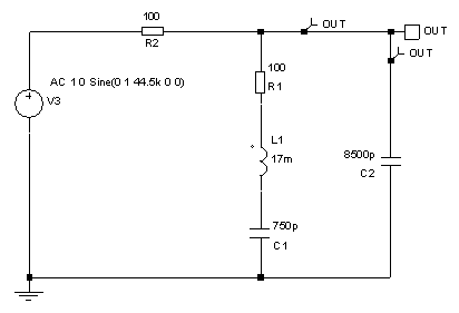
I've had a go at the ac simulation. I set the LC components L1 and C1 to give a resonance at around 100KHz, provided it with an ac source at 100KHz and did an ac analysis around 90-110KHz. LTspice wanted a ground node so I added an arbitrary large resistor with a ground. I've added pics of the circuit and output and zipped the LT circuit.

I'm finding it a little difficult intrepreting the results. The current and volts seem to be in -db, so I'm guessing that is attenuation but I'm not sure. I'll have another look tomorrow.

Thanks,

Ant.
 

Status
Not open for further replies.

Similar threads

Part and Inventory Search

Welcome to EDABoard.com

Sponsor

Back
Top