udhay_cit
Full Member level 6
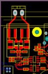
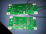
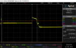
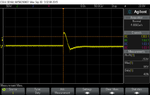
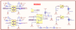
I'm designing a RS-485 communication device for CE & UL standard certifications. My test standard is ±2KV (IEC61000-4-5). We have In-house lab test facility with ESD, EFT, Signal line surge generator, etc., For my various protection circuit, I can't able to pass the test more then ±1.5KV. Please review my circuit & share your commands.
The attached waveforms & test run procedures are below..,
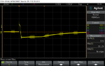
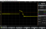
2kv_sig_pos (2kv signal surge positive)
04.gdt_bu_2k (bourns GDT parallel with surge generator)[measured across A & GND point]
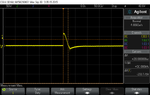
05.gdt_bk_2k (brightkings GDT parallel with surge generator)[measured across A & GND point]
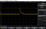
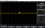
06.gdt_bu_tvs_2kv1 (bourns GDT & SMAJ6.5CA TVS diode parallel with surge generator)[measured across A & GND point]
07.gdt_bk_tvs_2kv1 (brightkings GDT & SMAJ6.5CA TVS diode parallel with surge generator)[measured across A & GND point]
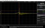
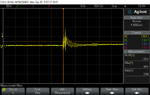
08.gdt_bk_tvs_2kv_ab (brightkings GDT & SMAJ6.5CA TVS diode parallel with surge generator)[measured across A & B point (differential)]
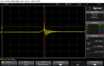
09.gdt_bk_res_tvs_2kv_ab (brightkings GDT, 10ohms resistor(between GDT & TVS) SMAJ6.5CA TVS diode parallel with surge generator)[measured across A & B point (differential)]
As per bourns "RS-485 PORT PROTECTION EVALUATION BOARD1" design notes, I changed my design as GDT, TBU(series), TVS. But this configuration also doesn't help me. The waveform similar to GDT+Resistor+TVS configuration.
Measurement tools are,
Oscilloscope (Agilent DSO-X 3014A, 100MHz)
Active differential probe (Pintek DP-150 PRO)
Surge generator (EMC Partner TRANSIENT 3000)
RS-485 Transceiver (MAX485)
GDT ( Bourns 2030-23T & brightking 2RL230M-6)
TVS (Vishay SMAJ6.5CA)
Regards
Udhay
The attached waveforms & test run procedures are below..,
2kv_sig_pos (2kv signal surge positive)
04.gdt_bu_2k (bourns GDT parallel with surge generator)[measured across A & GND point]
05.gdt_bk_2k (brightkings GDT parallel with surge generator)[measured across A & GND point]
06.gdt_bu_tvs_2kv1 (bourns GDT & SMAJ6.5CA TVS diode parallel with surge generator)[measured across A & GND point]
07.gdt_bk_tvs_2kv1 (brightkings GDT & SMAJ6.5CA TVS diode parallel with surge generator)[measured across A & GND point]
08.gdt_bk_tvs_2kv_ab (brightkings GDT & SMAJ6.5CA TVS diode parallel with surge generator)[measured across A & B point (differential)]
09.gdt_bk_res_tvs_2kv_ab (brightkings GDT, 10ohms resistor(between GDT & TVS) SMAJ6.5CA TVS diode parallel with surge generator)[measured across A & B point (differential)]
As per bourns "RS-485 PORT PROTECTION EVALUATION BOARD1" design notes, I changed my design as GDT, TBU(series), TVS. But this configuration also doesn't help me. The waveform similar to GDT+Resistor+TVS configuration.
Measurement tools are,
Oscilloscope (Agilent DSO-X 3014A, 100MHz)
Active differential probe (Pintek DP-150 PRO)
Surge generator (EMC Partner TRANSIENT 3000)
RS-485 Transceiver (MAX485)
GDT ( Bourns 2030-23T & brightking 2RL230M-6)
TVS (Vishay SMAJ6.5CA)
Regards
Udhay
Attachments
-
 2kv_sig_pos.png21.1 KB · Views: 209
 -
 04.gdt_bu_2kv.png22.3 KB · Views: 175
 -
 05.gdt_bk_2kv.png23.2 KB · Views: 165
 -
 06.gdt_bu_tvs_2kv1.png24 KB · Views: 164
 -
 07.gdt_bk_tvs_2kv.png24.1 KB · Views: 194
 -
 08.gdt_bk_tvs_2kv_ab.png22.2 KB · Views: 175
 -
 09.gdt_bk_res_tvs_2kv_ab.png23.7 KB · Views: 358
 -
Bourns_FU1106_RS-485_Evalboard_DesignNote_1.pdf392.5 KB · Views: 113
-
2R-6-SERIES_141202.pdf204.4 KB · Views: 129
-
2030-xxT-SM.pdf317 KB · Views: 137
-
 MODBUS.PNG64.8 KB · Views: 2,775
 -
 20151001_185916.jpg576.3 KB · Views: 466