T
treez
Guest

Hello,
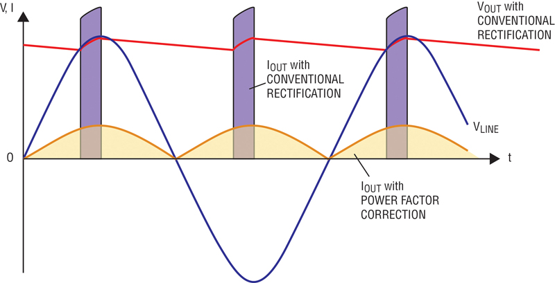
The below waveform shows the current in the secondary diode of an offline , power factor corrected flyback.
Clearly there is a strong 100Hz fundamental.
Being so low in frequency, this will cause much heating in the output electrolytic capacitor.
However, what is the RMS value of the 100Hz fundamental?…..is it the same value as the RMS value of the overall current? (in LTspice this comes out as 1.78A RMS)
LTspice gives the average value of this current as 1.16Amps.
So the question is, what is the RMS value of the 100Hz fundamental current?
LTspice simulation attached ("PFC flyback"), also the diode current waveform over 10ms is shown, and a zoomed in version of it.
(also attached is the “TIME FILE.txt”, which needs to be in the same folder as the simulation.


