Continue to Site

Welcome to EDAboard.com

Welcome to our site! EDAboard.com is an international Electronics Discussion Forum focused on EDA software, circuits, schematics, books, theory, papers, asic, pld, 8051, DSP, Network, RF, Analog Design, PCB, Service Manuals... and a whole lot more! To participate you need to register. Registration is free. Click here to register now.

Ripple Effect on RF Amp Design

Status
Not open for further replies.

@YY

Member level 2
Member level 2
Joined
Oct 29, 2009
Messages
45
Helped
0
Reputation
0
Reaction score
0
Trophy points
1,286
Visit site
Activity points
1,682
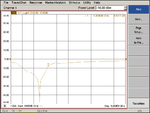
Hi, I have designed a RF amp at frequency 5.3GHz. Would like to know what is the root cause for the ripple effect along the band? Is it the unstable of the amplifier? or the not matching? or there is too much reflection?
 

Attachments

  • S21_x2@power-10.png
    S21_x2@power-10.png
    14.8 KB · Views: 104

It seems to me this effect could be due to a long (referred to lambda) poorly matched transmission line. Is your network analyzer calibrated at the end of the connecting cables ? Can't you measure S11 and/or S22 ?
 

It seems to me this effect could be due to a long (referred to lambda) poorly matched transmission line. Is your network analyzer calibrated at the end of the connecting cables ? Can't you measure S11 and/or S22 ?

Hi, yes, i have measured S11 too. as per attached is the result of measured value for S11. S11_x2@power-10.png
 

May be caused by poor match of your RF amplifier on the input or output, i.e. VSWR.
You can insert a PI attenuator at the input to see what happens.
 

Yeah looks like some weak oscillation or other interfering signal. Try reducing your IF bandwidth and see if it changes.
 

Hi, is there any term for this problem? Is there any suggestion for the reading?
 

Status
Not open for further replies.

Part and Inventory Search

Welcome to EDABoard.com

Sponsor

Back
Top