Z
zenerbjt
Guest
Hi,
The Nichicon SMR series 150uF , 400V electrolytic capacitor says it has a tan delta of 0.15.
Also, its ripple current rating is stated as 1.3 * 1.41 ~ 1.83A at 33kHz.
Howcome its only rated for 1.83A of ripple current.?
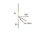
The ESR = tan delta * Xc = 0.15 * 1/(2.pi.33000.150E-6) = 4.83milliOhms.
With 1.83A of ripple current, the dissipation is only 0.016W. That’s very very low. Surely it can manage more than 1.83A of ripple current?
Nichicon SMR series 150uF,400V
**broken link removed**
The Nichicon SMR series 150uF , 400V electrolytic capacitor says it has a tan delta of 0.15.
Also, its ripple current rating is stated as 1.3 * 1.41 ~ 1.83A at 33kHz.
Howcome its only rated for 1.83A of ripple current.?
The ESR = tan delta * Xc = 0.15 * 1/(2.pi.33000.150E-6) = 4.83milliOhms.
With 1.83A of ripple current, the dissipation is only 0.016W. That’s very very low. Surely it can manage more than 1.83A of ripple current?
Nichicon SMR series 150uF,400V
**broken link removed**