neazoi
Advanced Member level 6

- Joined
- Jan 5, 2008
- Messages
- 4,157
- Helped
- 13
- Reputation
- 26
- Reaction score
- 15
- Trophy points
- 1,318
- Location
- Greece
- Activity points
- 37,198
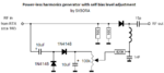
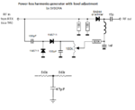
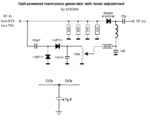
I have a diode multiplier circuit http://lea.hamradio.si/~s57uuu/astro/sidi_debug/harmgen_w_rtx.htm and I need to somehow take DC out of the 1w RF signal.
Is that possible? how?
Is that possible? how?