alaa1231
Newbie level 4

- Joined
- Feb 1, 2012
- Messages
- 6
- Helped
- 1
- Reputation
- 2
- Reaction score
- 1
- Trophy points
- 1,283
- Activity points
- 1,314
Hello
can anyone help me
I want to understand something about blocking in texas instruments datasheet c1101
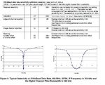
I this attached file , in the table it talk about blocking @ 2 Mhz and 10 mhz has values -50 and -40 dbm then in graph it show selectivity
is this graph show the attenution for these blockings for example @ 10 mhz in graph it show value = 50 db is that the attenuation for block coming of value of -40dbm (as from table ) also what is meant by @ 0 mhz selectivity is -12db is that gain!!!!!!!!!!
Second
We use here gfsk modulation what is bandwidth at (if) frequency ,I mean fc is it equal Fif +(channel spacing)/2 = 304 + 750/2 =679k is that right

