Continue to Site

Welcome to EDAboard.com

Welcome to our site! EDAboard.com is an international Electronics Discussion Forum focused on EDA software, circuits, schematics, books, theory, papers, asic, pld, 8051, DSP, Network, RF, Analog Design, PCB, Service Manuals... and a whole lot more! To participate you need to register. Registration is free. Click here to register now.

RF Balun test-bench confusion

anh56789

Newbie level 5
Joined
Jul 27, 2023
Messages
9
Helped
0
Reputation
0
Reaction score
0
Trophy points
1
Activity points
109
Hello,
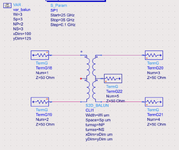
I am designing an RF balun to transform 50 Ohm single-ended to 100 Ohm differential. I used the Coilsys tool in ADS to auto-generate the EM model of the balun. I use 3 ports test bench for simulating the S parameters of the EM balun as the below figure.
grounded_port_TB.PNG

The simulation results are quite bad, the input return loss is only > 16dB and the amplitude and phase imbalance are 1.3 dB and 45 degrees at Ka-Band.
grounded_port_results.PNG


But when I removed the ground at the output ports ( 2 and 3) the results are different from the first one. Here are the ungrounded test bench and its results. The return loss, amplitude, and phase imbalance are quite good when compared to the previous results. The return loss is > 28dB. The amplitude and phase imbalance are nearly zero.
un_grounded_port_TB.PNG
un_grounded_port.PNG


I'm quite confused about the S parameter testbench. With the ungrounded test bench. The results are good. But I think when using this test bench, the effect of the parasitic capacitor from the secondary inductor to the substrate and primary inductor is removed due to the differential port ( as mentioned in this post https://muehlhaus.com/support/ads-application-notes/inductor-em-ports). Am I correct? Any insight on this problem would be appreciated. Thank you so much!!!
 
Why don't you use connect the Differential Port in Balanced Configuration.
And also, why CS and CP values are different ?? They must be identical.
The first configuration is correct but capacitors values are different therefore results seem inconsistent.
 
Why don't you use connect the Differential Port in Balanced Configuration.
And also, why CS and CP values are different ?? They must be identical.
The first configuration is correct but capacitors values are different therefore results seem inconsistent.
Hi BigBoss,
Thank you for your quick response!
What do you mean when you said
connect the Differential Port in Balanced Configuration
I may not understand you. But in my test bench, I want to use 2 ports at the output of the balun so that I can simulate the amplitude and phase mismatch between two output differential signals.
"And also, why CS and CP values are different ?? They must be identical." - As I mentioned above I want to transform a 50 Ohm single-ended signal to a 100 Ohm differential signal. These two capacitors are used for impedance matching. For good matching, their value needed to be different from each other.
Why do their value must be identical? I did run the simulation with CS=CP=200fF but the difference between the two test benches remains. Here are the test bench and results. The blue line is for ungrounded ports, the red line is for grounded ports.
Test_bench_identical_CS_CP.PNG
identical_CS_CP_results.PNG


Can you supply 4-Port S-Parameters of your Transformer ?? Let the Midpoints are floating and do a simple 4-Ports S-Parameters simulation with 50 Ohm Zo then post it here. Let's check the imbalance the Transformer.
 
Can you supply 4-Port S-Parameters of your Transformer ?? Let the Midpoints are floating and do a simple 4-Ports S-Parameters simulation with 50 Ohm Zo then post it here. Let's check the imbalance the Transformer.
Hi BigBoss,
This is my test bench for the SP export and the s4p file for the balun.

SnP_export.PNG
 

Attachments

  • S2D_BALUN.s4p.txt
    53.9 KB · Views: 73
OK, There is a huge imbalance between the Ports. If you optimize to get best Reflection Loss , you loose Phase Imbalance. If you optimize the balun to get best Phase Imbalance, you loose reflection Losses.
There might also be some interpolation errors because the touchstone file that you have supplied is very coarse.
If you simulate the Balun itself with much finer frequency steps( 10MHz) , I can say something clearer.
Phase Imbalance is pretty bad and there is no way to correct with serial capacitors. There-I guess- are some geometrical mistakes there.
1690580180655.png

What could you obtain from CoilSys, can you post here the layout ??
 
Hi,
I can only export the S2P file from 25 to 35GHz with a 100 MHz step size due to some security problems. In this file, I also export the center tap of the balun at the output as shown in the test bench.
TB_5port.PNG
Balun_layout.PNG

You can connect the center tap of the balun to the ground to improve the imbalance. But what makes me confused is which test bench should we choose to evaluate the performance of the balun, the one with grounded output ports or not grounded??? and Why? Here are the two test benches that I don't know which one is the correct one.
grounded_port_TB.PNG
un_grounded_port_TB.PNG
 

Attachments

  • S2D_BALUN.s5p.txt
    110.6 KB · Views: 63
  • 1690615254552.png
    1690615254552.png
    149.8 KB · Views: 66
But what makes me confused is which test bench should we choose to evaluate the performance of the balun, the one with grounded output ports or not grounded??? and Why?
The test setup should be selected acccording to application case. It's quite unlikely that your application involves a load with infinite common mode impedance as modelled by the ungrounded output ports. So grounded ports seems a natural choice.

Layout geometry clarifies why you get asymmetrical behaviour.
Hi FvM,
Thank you for your response!!!. I may not understand you well. Could you explain more?
If I connect the output of the balun to a 100 Ohm differential CPW, which load should I choose for the balun? When I use 2 ungrounded ports (50 Ohm each) the input return loss (S11) is quite good (>26dB) and this result stays the same when using a 100 Ohm port at the output put. But with 2 grounded ports (50 Ohm each) the S11 is worse (>16dB) at Ka-Band as shown in the above figures (my first post).
 
When you attach ground where the loads join (at right-hand in schematic), I keep seeing the equivalent of a 25 ohm load (two 50 ohm loads in parallel).

So my simulation has the two loads as 100 ohms each. Furthermore there is an alternate way the LC can be arranged when you want impedance matching. If you connect the 100 ohm resistors then it combines two out-of-phase signals as a differential signal.
I adjusted values so that power (Watts) appears to be maximized (because that's usually the goal of impedance matching). I used 25 GHz, 300 nH, 100 fF.

impedance matching n simultaneous signal splitting via xfmr as LC arrangement.png
 
If I connect the output of the balun to a 100 Ohm differential CPW, which load should I choose for the balun?
Grounded configuration better fits the CPW load. To model a specific CPW exactly, you need to know its common mode impedance (e.g. CPW with or without ground, different substrate thickness), which could be added to the test setup. But it's unlikely that you get much improvement in balun measurements. Its lack of symmetry is real, it just reflects the layout, as stated by BigBoss.
 

LaTeX Commands Quick-Menu:

Part and Inventory Search

Welcome to EDABoard.com

Sponsor

Back
Top