Continue to Site

Welcome to EDAboard.com

Welcome to our site! EDAboard.com is an international Electronics Discussion Forum focused on EDA software, circuits, schematics, books, theory, papers, asic, pld, 8051, DSP, Network, RF, Analog Design, PCB, Service Manuals... and a whole lot more! To participate you need to register. Registration is free. Click here to register now.

Reverse sawtooth generator schematic needed with discrete components

Status
Not open for further replies.

neazoi

Advanced Member level 6
Joined
Jan 5, 2008
Messages
4,123
Helped
13
Reputation
26
Reaction score
15
Trophy points
1,318
Location
Greece
Activity points
36,955
Hello,
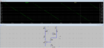
I need a reverse sawtooth generator made with discrete components. It will be used to drive a varicap in a sweep generator and to trigger a scope.
I have found a similar circuit here http://www.vk2zay.net/article/196 see the first schematic of the linear voltage ramp http://www.vk2zay.net/article/file/902
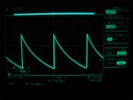
Is there any way to make it such that I can get reverse pulses in the output? I do not mean negative, I mean to begin with a sharp positive edge and then to linearly decay to 0v.
 

Attached is a version of the last (Update) circuit shown in your reference with the transistors and diode inverted in polarity, and the power and ground interchanged to get the inverted sawtooth.

Note that you should add filter capacitors of say 0.1µF and 10µF across the circuit (not shown) from V+ to ground.

Sawtooth Inverted.gif
 
  • Like
Reactions: neazoi

    neazoi

    Points: 2
    Helpful Answer Positive Rating
Attached is a version of the last (Update) circuit shown in your reference with the transistors and diode inverted in polarity, and the power and ground interchanged to get the inverted sawtooth.

Note that you should add filter capacitors of say 0.1µF and 10µF across the circuit (not shown) from V+ to ground.

View attachment 99066
Thank you so much! this is really helpful!
I wonder if the first schematic of the linear ramp can be inversed too? I am asking for this because he refers to the first schematic as amplitude steady when the frequency changes.
I would appreciate if you could help on this.
 

The circuit I posted is also essentially amplitude steady with frequency if C1 is changed to vary the frequency.

Edit: What frequency range do you need?
 
Last edited:

The circuit I posted is also essentially amplitude steady with frequency if C1 is changed to vary the frequency.

Edit: What frequency range do you need?

0-1KHz max, short of
 

In order to get to 1kHz at full amplitude I had to change Q2 and Q4 to 2N2369, Q3 to 2N5771 with C1 = 1nF.
 
  • Like
Reactions: neazoi

    neazoi

    Points: 2
    Helpful Answer Positive Rating
In order to get to 1kHz at full amplitude I had to change Q2 and Q4 to 2N2369, Q3 to 2N5771 with C1 = 1nF.

Why is that needed? I thought generalized transistors should work as long as the frequency is kept low.
Can you test complements 2n2222 and 2n2907 (which I have available), to see how it responds?
 

Yes, those generalized transistors should work at those frequencies. I did some troubleshooting on the simulation and determined that the diode in the base circuit of Q4 was causing premature triggering of the capacitor reset due to capacitive coupling of the emitter signal to the base of Q4. I solved this by placing diode D1 in series with the emitter of Q4 instead of the base (its purpose is to prevent reverse breakdown of the base-emitter junction). That allowed proper operation with two 2N2222's and a 2N2907. It does reduce the peak positive voltage by about 0.7V but hopefully that's not a problem for you.

Note I also changed R2 from 1k to 1.5k for better waveform linearity at the bottom of the trace.

Edit: Below is the revised circuit.

Sawtooth Inverted.gif
 
  • Like
Reactions: neazoi

    neazoi

    Points: 2
    Helpful Answer Positive Rating
Yes, those generalized transistors should work at those frequencies. I did some troubleshooting on the simulation and determined that the diode in the base circuit of Q4 was causing premature triggering of the capacitor reset due to capacitive coupling of the emitter signal to the base of Q4. I solved this by placing diode D1 in series with the emitter of Q4 instead of the base (its purpose is to prevent reverse breakdown of the base-emitter junction). That allowed proper operation with two 2N2222's and a 2N2907. It does reduce the peak positive voltage by about 0.7V but hopefully that's not a problem for you.

Note I also changed R2 from 1k to 1.5k for better waveform linearity at the bottom of the trace.

Edit: Below is the revised circuit.

View attachment 99084

Thank you very much for your time!
I will try this circuit in practice and let you know.

I worry a little bit about the current that it can supply. The purpose is to use it to drive:
1. XY of a scope
2. small HF toroids windings, for some experiments.

In some cases the current drawn by the load (connected directly to the capacitor) may discharge the capacitor hardly, so that it is not allowed to be charged by the constant current source. Maybe a current amplifier at the output could solve this, or maybe I am totally wrong
 

The schematic is essentially an SCR made from the PNPN junctions of the top transistors. It works rather like a unijunction oscillator and perhaps that is another line of investigation to follow.

I'm wonderig why the existng X timebase output of the oscilloscope isn't being used. It is a sawtooth, and even if it wasn't it wouldn't matter as it will always track the position across the scope screen. I also gives you the ability to sweep at whatever speed you want without changing any component values.

Brian.

There are two problems on this.
First this timebase it not always present in all scopes and one has to dig into the scope circuits to access it.
Second, The generator can be used for other experiments (2) independent of the scope.

That is why i am wondering for the current if it can be amplified, whereas the voltage ramp still remains linear.
 

........................
I worry a little bit about the current that it can supply. The purpose is to use it to drive:
1. XY of a scope
2. small HF toroids windings, for some experiments.

In some cases the current drawn by the load (connected directly to the capacitor) may discharge the capacitor hardly, so that it is not allowed to be charged by the constant current source. Maybe a current amplifier at the output could solve this, or maybe I am totally wrong
Yes for any significant load you will need to add an op amp buffer or emitter follower amplifier stage.
 

Yes for any significant load you will need to add an op amp buffer or emitter follower amplifier stage.

could you suggest an example of an emitter follower amplifier stage and how it can be coupled to the output of the circuit?
 

Here is a true linear ramp designed by me quite awhile ago based on the same concept, although the peak is not really sharp, R1 can be adjusted for a wide range of freq, Sim looks good, in practice, I have not tested it. Just in case you might be interested.
 

Attachments

  • DSO.PNG
    DSO.PNG
    45.5 KB · Views: 133
  • Like
Reactions: neazoi

    neazoi

    Points: 2
    Helpful Answer Positive Rating
Here is a true linear ramp designed by me quite awhile ago based on the same concept, although the peak is not really sharp, R1 can be adjusted for a wide range of freq, Sim looks good, in practice, I have not tested it. Just in case you might be interested.

Where do you get the output from?
 

Where do you get the output from?

at the cap, junction of Q3's E and Q1's C

PS: If you want a fuller swing, voltage divider can be set to 100k/10k ect...
 
Last edited:

Here is the circuit with an emitter follower output buffer. I used a Sziklai pair (complementary Darlington) output to minimize loading of the circuit. It's similar to a Darlington stage but has only one diode offset instead of two from input to output. You could use the same buffer for iimagine's circuit.

Note that R6 can be an external load in place of the circuit resistor.

Sawtooth Inverted.gif
 
Last edited:
Ok I build the last circuit. Attached is the waveform. Better than the capacitor discharge curve but not very linear.
the waveform is the same either I connect the output amplifier or not.

Also when the power amplifier is connected it draws 200mA. The 2n2907 gets really hot, can't touch.

Any ideas to solve these problems?
 

Attachments

  • 111.jpg
    111.jpg
    34.4 KB · Views: 124

OK. I neglected to observe the power dissipated in Q5. :sad: It does average about 500mW with a 50Ω load. The load should be no smaller than about 100 to 200Ω or so (depending upon the package style and dissipation rating for the 2N2907) to keep the temperature within reasonable limits.

Don't know why the output is so non-linear. Are you sure it's all wired correctly and all parts are the correct type and values? I'd double check that, especially around R1 and R4.

Your frequency is only about 30Hz. What value of capacitor C1 are you using?
 
  • Like
Reactions: neazoi

    neazoi

    Points: 2
    Helpful Answer Positive Rating
Better than the capacitor discharge curve but not very linear.

Which circuit are you referring to?

Are you using the exact components and voltage as in crutschow's drawing? Because if the applied voltage is lower than 12V, noticeable non-linearity can be seen from LTSpice sim. This method, bootstrapping discharge, will not give you a true linear waveform.
 
  • Like
Reactions: neazoi

    neazoi

    Points: 2
    Helpful Answer Positive Rating
Status
Not open for further replies.

Similar threads

Part and Inventory Search

Welcome to EDABoard.com

Sponsor

Back
Top