Continue to Site

Welcome to EDAboard.com

Welcome to our site! EDAboard.com is an international Electronics Discussion Forum focused on EDA software, circuits, schematics, books, theory, papers, asic, pld, 8051, DSP, Network, RF, Analog Design, PCB, Service Manuals... and a whole lot more! To participate you need to register. Registration is free. Click here to register now.

[SOLVED] Reverse polarity detection (I need an idea)

Status
Not open for further replies.

lighty

Member level 3
Joined
Oct 2, 2002
Messages
57
Helped
4
Reputation
8
Reaction score
4
Trophy points
1,288
Location
Universe
Activity points
490
I need a general idea on a way to measure (or at least detect) reverse polarity signals by PIC ADC.

I'm designing a pulse charger for lead-acid batteries. Voltage ratings of batteries is from 6 - 48V. MCU is measuring potential over the charging cap in order to determine voltage to be dumped into the battery. A simple voltage divider does the trick and there is no problem there (although with such extended potential range resolution is lost, especially on 10-bit ADC).

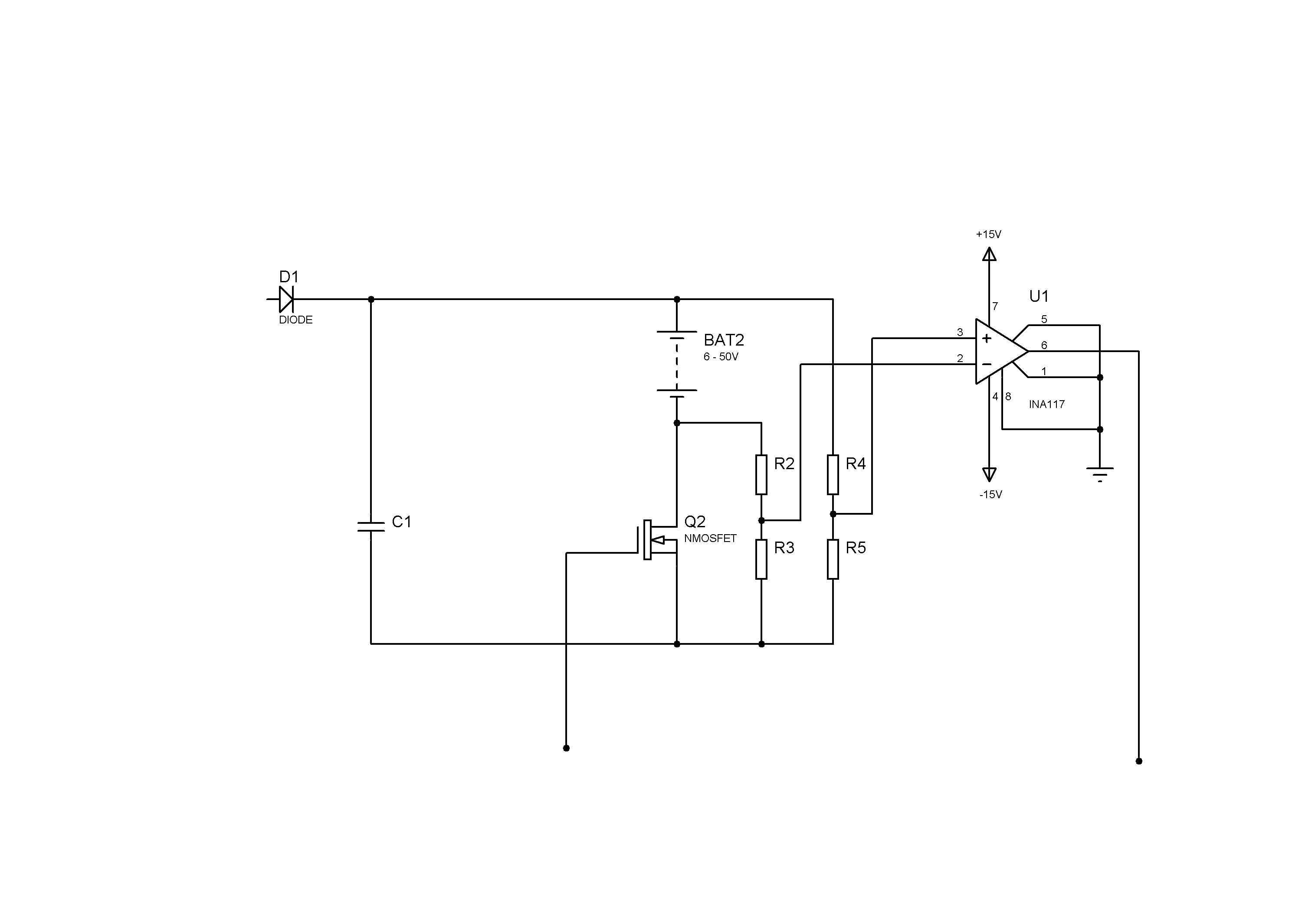
However, MCU also needs to take into account the voltage of the battery and MCU is measuring battery voltage through differential OPAMP (there is also inherent loss of resolution by fixed sets of voltage dividers but that's also not a problem).

Now, what bothers me is how to detect if battery polarity is reversed ie how to detect if battery is connected in reverse. Analogue part of the circuit is not a problem and with dual power supply the output of differential OPAMP will correspond to the reversed polarity. However, MCU ADC can't handle that and also input will probably get damaged if differential OPAMP output is lower than Vss by more than 0.3 V.

Let's say, for the sake of the argument, that I want to measure inverted voltage. I could of course invert signal by adding additional OPAMP but it has to be done automatically by MCU or by some analogue design (which is of course advisable).

Even just a detection of reverse polarity would be a good solution in order to prevent MCU to start charging process. However, the reverse polarity detector must be done in a way that would be able to indicate to MCU that polarity is reversed without damaging ADC input.

I considered using a single power supply to feed the differential OPAMP which would prevent its output from going negative. However INA117 is AFAIK not capable of going rail to rail and that could present a problem, especially with such a wide voltage range to be measured. Even if it's possible to get INA117 to go rail to rail with acceptable error in lower range I still have the challenge of designing a reverse polarity detector that would signal to MCU that battery is connected in reverse.

The schematic is just a general idea to convey the concept of what I'm thinking and I'm open for suggestions.

Any ideas are appreciated.


BTW - I hope I'm posting this to correct section of the forum.


Dear Lighty
Hi
I thing your circuit has a problem .
As we know the drain of Nmosfet ( enhancement ) should connect to positive voltage , otherwise , it can't work .
best Wishes
Goldsmith
 

Your ADC input should already have clamp Schottky diodes internally tied to the power supply (VCC and gnd), these can protect the input as long as there is an external resistance that will limit the current through these diodes.
These diodes limit the input to GND-0.3v to Vcc+0.3v.
You can also add your own diodes externally (Schottky)

Please take a look at
https://www.cirrus.com/en/pubs/appNote/an20.pdf

---------- Post added at 01:25 ---------- Previous post was at 01:22 ----------

I thing your circuit has a problem .
As we know the drain of Nmosfet ( enhancement ) should connect to positive voltage , otherwise , it can't work .

He is just using the Nmosfet as a low side switch why is that a problem?
 

Hi dear Alex
It has problem , because , the minus polarity of supply ( 6-50v ) connected to the drain of Nmosfet !! isn't it ?
Best Regards
Goldsmith
 

@goldsmith

As a matter of fact MOSFET switch works normally. ;-)

Relatively speaking drain of MOSFET is on negative polarity of battery but in absolute terms it is more positive than common ie more positive than source of MOSFET.
 

Hi dear Alex
It has problem , because , the minus polarity of supply ( 6-50v ) connected to the drain of Nmosfet !! isn't it ?
Best Regards
Goldsmith

Are you referring to a problem if the batteries connect in reverse or as shown in the schematic?
 

@alexan_e

I'm referring to a problem if the battery connects in reverse.

To be honest I'm embarrassed that I forgot about internal clamping diodes. Series resistor is certainly an easy solution to protect input.


However, I still have to devise some way to detect reverse polarity and to prevent MCU from starting a charging procedure.
 
Last edited:

As shown in the circuit , the polarity of drain is negative , even the input voltage through diode is very high !
See it again , please .
Respectfully
Goldsmith
 

@goldsmith

Trust me, it works normally. You're confusing relative and absolute potential polarity that MOSFET sees.

Try it for yourself.;-)
 

No problem if it worked .
But how !!!! :-D can you tell me , please?
Thanks

---------- Post added at 03:11 ---------- Previous post was at 03:10 ----------

Is the down line , ground too ?
 

It works because what opens N-channel MOSFET is positive Vgs (higher than Vth).

In this circuit common is shared between MCU and MOSFET so any positive voltage applied to gate by MCU (relative to common) that is higher than Vth will open MOSFET.
 

As shown in the circuit , the polarity of drain is negative , even the input voltage through diode is very high !
See it again , please .
Respectfully
Goldsmith

The mosfet is a simple low side switch configuration, it "provides ground" to the batteries minus side when on or has a high resistance when off so the minus battery side is like floating.
Why do you say negative voltage the battery minus will have a higher voltage with reference to the ground.

@alexan_e

I'm referring to a problem if the battery connects in reverse.

To be honest I'm embarrassed that I forgot about internal clamping diodes. Series resistor is certainly an easy solution to protect input.

However, I still have to devise some way to detect reverse polarity and to prevent MCU from starting a charging procedure.

The reverse polarity would be seen as a 0v input so the charge will not start, isn't that enough?
Maybe you can also connect a led that turns on (not using the mcu) when the battery is reversed to notify the user.
If you want to detect this in the mcu program then you probably need to use an additional pin.
 

@alexan_e

Well, that's the whole point. I have spare pins on MCU and that's not the problem. I'm simply looking for the simplest way to trigger that pin when opposite polarity is present.

BTW - what do you mean that reverse polarity will be seen as 0V? Diodes will clamp negative output from differential OPAMP output to Vss -0.3V, that's true but for MCU that means two things. Either the voltage of battery is very low or it has reversed polarity. I need to know exactly which is which.

LED idea is OK, but the voltage range of battery is so wide that a single series resistor wouldn't suffice to cover it entirely without either burning the diode or not lighting it. And besides I really need MCU to know what is happening.
 

lightly
I think the mosfet model that you selected has , internally , diode , in parallel with DS that called , anti parallel diode , thus it could conduct !
See below , please:

When the VGS is zero , the current is about infinite ! ( the internally diode , conducted )
mosfet.JPG
Regards
Goldsmith
 

You've misread my schematic. The battery in your schematic is connected parallel to MOSFET. In my schematic I'm using MOSFET as a low side switch (as alexan_e already told you). Redraw my schematic exactly as it is.
 

oops , yes , you're completely right , and it will work , i miss understood , your schematic .Sorry .
Best Wishes
Goldsmith
 

No need to apologize. I'm glad that you've learned something. ;-)

However, I'm still stuck with the problem of providing MCU with the correct information about reverse polarity.
 

BTW - what do you mean that reverse polarity will be seen as 0V? Diodes will clamp negative output from differential OPAMP output to Vss -0.3V, that's true but for MCU that means two things. Either the voltage of battery is very low or it has reversed polarity. I need to know exactly which is which.

Usually chargers don''t start a charge cycle when they detect dead batteries so if your battery gives a reading of 0v (even in correct polarity ) would you start charging it?
 

As a matter of fact very low voltage (almost dead) lead-acid batteries can sometimes be revived by desulfators (at least to a certain degree). So of course I'm interested in providing MCU with correct information. In this case it is important for me to know if the battery simply has very low voltage or if it's reversely polarized. And in this case resolution of battery voltage measurement will be rather poor due to wide range of voltage to be measured (6-50V) and MCU will have a hard time determining what's the case.

All in all, I would really like to provide it with proper information.
 

Can you take advantage of the voltage across the diode to drive a NPN transistor ?
Or maybe use a transistor with the BE connected across the battery so that the transistor conducts when the polarity is reverse but this will only work if the batteries have at least 0.6v

Another thought, when your batteries are connected in reverse wouldn't the diode prevent any current even if you start the charge?
This of course means that the batteries are protected but you still can't understand the wrong polarity unless maybe you also have a current measurement.
 

Status
Not open for further replies.

Similar threads

Part and Inventory Search

Welcome to EDABoard.com

Sponsor

Back
Top