Continue to Site

Welcome to EDAboard.com

Welcome to our site! EDAboard.com is an international Electronics Discussion Forum focused on EDA software, circuits, schematics, books, theory, papers, asic, pld, 8051, DSP, Network, RF, Analog Design, PCB, Service Manuals... and a whole lot more! To participate you need to register. Registration is free. Click here to register now.

Resistor mounting conditions for full power rating at 70degC ambient?

Status
Not open for further replies.
That is impossibly hot, not only for the solder but the board. it will go black very quickly and probably de-laminate.
Thanks, sorry to keep asking but youre raising some incredibly good points here…specially since we are doing a load of smps’s on a pcb that’s not mounted with a heatsink at the bottom of itself, and with 70degC internal ambient temperature and no vents in the enclosure, and all of our components are SMT only.
Do you know what is the temperature of the PCB at which the blackening and delamination that you spoke of starts happening?
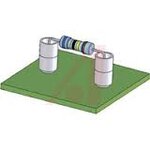
 

My own long term experience is that any board mounted component that has a surface temperature of 80C will blacken a board over time.
That is not temperature rise, but absolute surface temperature.

Resistors must be greatly de-rated, If the resistor is specified as 25 watts dissipation at 250C rise, something like 3 watts would be realistic, giving 30C rise in a 40C ambient.
That 70C would still be capable of leaving a painful burn on the tip of your finger at 3 continuous watts.
It would still need to be mounted on ceramic spacers above the board,and be through hole, and have very generous pad areas.
The ceramic beads pull an amazing amount of heat out of the leads, and provide much more surface area so the solder pad can run much cooler than the resistor body.

ceramicstandoff.jpeg


Anything much bigger than that needs to be an aluminium clad resistor bolted to a heat sink.

My own "rule of thumb" for designing ANYTHING, if I cannot hold my thumb on it indefinitely when its running absolutely flat out.
It gets redesigned.
 

Thanks, bearing in mind that in your above diagram the resistor body is at 70degC, then is the main job of the ceramic beads to ensure a decent length of metal lead for heat reasons, or to stop blackening of the board?

I have been asked to do eight 25W (28VIN, 1V5OUT,17A out) SMPS’s (sync bucks) side by side on a FR4 PCB which has no heatsink on its bottom surface due to processors being there (the water cooled heatsink is above the PCB and needs to be gap-padded to the SMT components).
Absolutely all components are SMT.
The internal ambient is 70degC.
There are no vents in the enclosure. The PCB is not necessarily mounted in such an orientation to allow good flow of convection currents over the PCB surface.
Do you think this is a sinking ship?
 
Last edited by a moderator:

Eight 25W each? That makes a total of 200W- water cooled heatsink can take out lots of heat- what is the total enclosure volume?
 

Thanks Yes the water cooled heatsink can, but it is only coupled to the fets and inductors by gap-pad....1.8w of each inductor's loss is in the windings , and only 0.4w in the core, so i reckon the inductors will be poorly thermally coupled to the water cooled heatsink...and i think the inductors are therefore going to heat the pcb up and do bad stuff to the sense resistors, controllers, etc, along with themselves.
 

Thanks Yes the water cooled heatsink can....

Sorry if I was not clear (now I know that for sure): just consider my way of thinking. You keep a heat source of 200W in a closed box and monitor the temp of the box walls in an ambient temp of 70C. If the box walls are nicely corrugated to convect and radiate 200W of power, it will all depend on the total surface area of the box. It may be barely possible if the 8 heat sources are nicely distributed all over the box. As your circuit is confined over a PCB, the heat sources mainly radiate in one direction (top side) and no simulation can be meaningful unless we know the size of the board and the position of the heat sources.

Is the water cooled heat sink actually dissipating 200W at 70C?
 

the "LOAD" dissipates 100W inside the enclosure. The eight SMPS's (these are also inside the enclosure) have each 6W of loss in their fets etc.
So the water cooled heetsink is required to act on the internal dissipation inside the enclosure, which amounts to 100W + 8*6w = 148W.
Its a bit of a secret so i cannot really say where the other 100w is actually going, but the other 100W is dissipated outside the enclosure and so that 100W's worth of dissipation is not the problem.....the 148W that gets dissipated inside the enclosure is the problem...and the water cooled heatsink is to deal with that.
 

So the water cooled heetsink is required to act on the internal dissipation inside the enclosure,.


It is possible but very unlikely that the water cooled heatsink is dissipating all the heat within the enclosure. In that case (if we have 150W heat being produced within the enclosure) and the enclosure must remove this total heat (150W) across this surface, we need to ask the question: what is the effective surface area and the actual steady state surface temperature (of the enclosure) of the enclosure (and this need to be less than or equal to the ambient temperature (70C) as specified.)

Certainly it is possible to take care of 6W of power dissipation at 8 distinct points with an ambient temp of 70C. But the size of the enclosure is needed for a good simulation. Else you need to have a highly corrugated surface for the enclosure cover.
 
  • Like
Reactions: treez

    T

    Points: 2
    Helpful Answer Positive Rating
Thanks, This is related to the above, and concerns the same resistor...

Hello,
Page 8 (top) of the below datasheet for the Resistor [1W,2512 , PR2512 resistor (2 milliohms)] states that if exposed to 70degC for 1000 hours, then it effectively says that it may have a resistance of +/-1% +0.0005 ohms. (presuming at RCWV)
https://www.farnell.com/datasheets/1563633.pdf

….0.0005 ohms is 12.5% of 2 milliohms.
This is really bad.

Can this be right? We don’t want our resistor packing up like this, this quickly.
 

then it effectively says that it may have a resistance of +/-1% +0.0005 ohms. (presuming at RCWV)

….0.0005 ohms is 12.5% of 2 milliohms..

I believe they mean R*(+/-)1%+0.0005 ohms;

if R is 1ohm, it simply means 1 (+/-)1*0.01+0.0005; that means the resistance will change by about (+/-)1% over this temp range;

The last +0.0005 is simply added to ensure that the smallest resistance will be 0.0005 (else it can become close to zero)
 

Status
Not open for further replies.

Similar threads

Part and Inventory Search

Welcome to EDABoard.com

Sponsor

Back
Top