Continue to Site

Welcome to EDAboard.com

Welcome to our site! EDAboard.com is an international Electronics Discussion Forum focused on EDA software, circuits, schematics, books, theory, papers, asic, pld, 8051, DSP, Network, RF, Analog Design, PCB, Service Manuals... and a whole lot more! To participate you need to register. Registration is free. Click here to register now.

Requesting Help for PIC 16F877 on elevator

Status
Not open for further replies.

cacing

Junior Member level 1
Joined
Sep 13, 2011
Messages
17
Helped
0
Reputation
0
Reaction score
0
Trophy points
1,281
Activity points
1,432
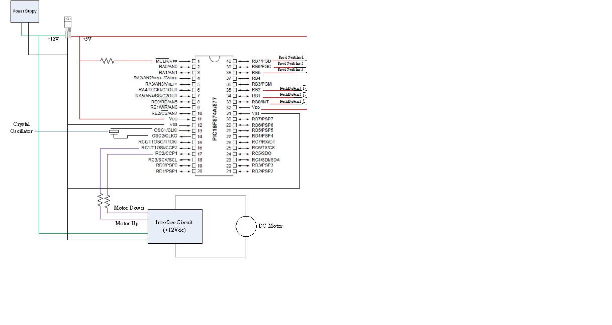
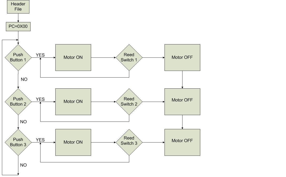
hello guys, i am currently on my final year and is doing my final project for an elevator.. but now i am stuck in the middle of process.. i already have a circuit and using a 12V power wiper motor to control the movement of the car.. i connect the circuit to the testing board and instead of using motor.. i am replacing the motor with 2 LED.. 1 LED for forward and 1 for backward.. but my LED never lights up.. i am using 3 push button and 3 reed switches as my input.. any one could help me with my current situation? pls kindly provide some comment or ur email so that we can have further discussion.. millon thanks to u guys :)
 

How about a schematic? There's no information here to offer any ideas.
 

i'm sorry.. i forgot to include that.. if i were to change the LED to a motor for testing.. do u think that would be better? as if will everything works?

---------- Post added at 04:07 ---------- Previous post was at 04:05 ----------

btw, the push button, reed switch and VDD are all connected to 5V.. it's not clear in the diagram
 

Better make a flowchart implmentng logic for desired operation. After that decide hardware details. And then write softare and perform trouble shooting.
What the buttons and reed switches are doing what processor should do when they give a positive signal. Make a diagram for them also decribing their functions.
 
I hope you've got series resistors with your leds, otherwise 12 volts will destroy them. Regardless, your schematic tells us nothing.

* Is your software working? How do you know?
* What is your interface circuit, other than a square that says "interface circuit"? Is it a box of weasels? Is it a container of dark matter?

First, verify that your software works. Then verify your "interface circuit" works (test it separately from the uP).
 

this is my flowchart.. basically mu hardware is just using Reed switch, 3 N/o push button, voltage regulator, a 12V power Wiper motor. i am just making a simple up and down elevator for 3 floor which is Ground, first floor and second floor.


@barry: my software i tried on MPLAB the workspace.. i am not sure whether how to test in exact.. any ideas? the interface circuit refers to H-BRIDGE connection.. sorry for the unclear information given.. i have already tested my circuit separately.. and it works perfectly fine.. i am planning to use a 3-5V small motor to test with my circuit instead of using my 12V motor for testing..

---------- Post added at 04:58 ---------- Previous post was at 04:57 ----------

and yup.. i have resistors to limit current too.. i am using a 5V battery for testing small circuits as the 12V motor is not connected for the moment because i am using LEDs for testing..
 

what help do you need now? i have never used PIC but i have done this project using 8051, keypad and 7 segment display! with 8 floors movement capability.
 

To test your software, I would just simulate the push button and reed switches, and verify that the appropriate outputs turn on/off.
Verify the states of your switches are as you intended (Normally open or normally closed)
Verify that the output level of your PIC is adequate to drive the H-Bridge.

You should also be able to run MPLAB in debug mode, to verify that your software is doing what it's supposed to while connected to actual hardware.

Also (maybe it's just an incomplete diagram) your flow chart shows no return from the "motor off" state.
 

@ucsam: now i have done my programming and everything and just left with the testing parts.. still checking out and finding ways to solve the problems occurs which cause my circuit not success..

@barry: the states of my switches are verified N/O already.. and initial i am using 12V supply to my H-Bridge and Regulator LM7805 5V for my PIC so that my PIC wont be damaged. and regarding my flow chart, when the motor is off.. meaning all the operation is temporarily stopped until another input is given... i dun think there is a need for it to show a return right? and for MPLAB, i try using Simulate and giving "fire" to my input (reed switches and push button).. it seems ok so far.. do u need a list of my programming as well?

p/s: i am quite rush with my project now since i left with another 1month+ before my submission date.. thanks every1 for helping out..
 

In the interest of completeness you should show a return from the "motor off" state to the top of your flow chart. That's what really happens, isn't it?

Since you already have hardware built, you can use the debugger to test your software and hardware together. Put a breakpoint at the place where the code jumps to the "motor on" state, and you should see the software stop at that point when you push the button. If that works, then put a breakpoint at the place where you read the reed switch, and verify that it reads the switch properly (that the switch is closed). If the reed switch is open, you'll never see the motor turn on, right? Verify that the output to the interface circuit is on.

That should give you something to start with.
 

Switches are for calling and reed switches detects that the lift has reached the floor, right? now if switch of 1st floor is pressed how will processor decide wheather to run motor upwards or downwards{lift is either on ground floor or on second floor).
It is amost necessary to incorporate upper and lower limit swiches. A siron sound when malfunction detected ({for example motor does not reach the floor in a maximum allowed time or door open does not detected)and to get attention of th calling part if is too busy watching people going rapidly through the stairs.Next step may be inner and outer digital readouts
for lift position. This will make your project more facinating or you'r going simple?
 

@barry: yeah now i understand what u mean.. i will add another line to complete my flowchart.. thanks a lot.. regarding the testing of simulation i will try it out... hopefully everything work successfully..

@alertlinks: the switches part are correct, the reed switches is to stop my motor.. example when i am in ground floor, and i press on 2nd floor switch. the reed switch on 2nd floor will stop the motor when the elevator reach 2nd floor.. basically thats wat my understanding about my reed switches. i think it's better u take a look at my programming..
MOVEFLOOR1: BTFSC PORTB, 6
GOTO CHECK
BTFSC PORTB, 5
GOTO ATTOP
BTFSC PORTB, 7
GOTO ATBTM
GOTO MOVEFLOOR1

ATTOP: BCF PORTC, 1
BSF PORTC, 2
CHECK2UP: BTFSS PORTB, 6
GOTO CHECK2UP
BCF PORTC, 2
BCF PORTC, 1
GOTO CHECK

ATBTM: BCF PORTC, 2
BSF PORTC, 1
CHECKDN: BTFSS PORTB, 6
GOTO CHECKDN
BCF PORTC, 1
BCF PORTC, 2
GOTO CHECK

---------- Post added at 07:00 ---------- Previous post was at 06:58 ----------

PORTC,1 = motor going down..
PORTC,2 = motor going up..
PORTB,5 = reed switch at 2nd floor...
Portb,6 = reed switch at 1st floor..
portb,7 = reed switch at ground floor.

---------- Post added at 07:01 ---------- Previous post was at 07:00 ----------

@alertlinks: the moment i just need to make my elevator going up and down.. not too facinating yet.. just making out a simple elevator going up and down.. so yeah.. i just need that to be success first before anything..
 

When you press the 2nd floor button how do you know whether to go UP(if the elevator is on 1) or down (if the elevator is on 3)? Do the reed switches tell you that?
 

yup. the reed switches act as sensor.. detecting the elevator.. thats why my program need to check on reed switches everytime after the push button input is being pressed. or do u want to have a look at my complete programming? and u can give me some feedback regarding it..
 

I suggest you try the the debugging steps I outlined. I hate debugging other peoples code. :)
 

alright.. i will try it out.. from the previous post of urs: "Since you already have hardware built, you can use the debugger to test your software and hardware together. Put a breakpoint at the place where the code jumps to the "motor on" state, and you should see the software stop at that point when you push the button. If that works, then put a breakpoint at the place where you read the reed switch, and verify that it reads the switch properly (that the switch is closed). If the reed switch is open, you'll never see the motor turn on, right? Verify that the output to the interface circuit is on."

u mean initial i put a breakpoint at all the port that will make my motor on.. and yea i tried.. the software will stop at the point when it pass by.. it will stop at the place where i put breakpoint at my motor on state.. then u said put a breakpoint at the place where u read the reed switch.. do i need to remove the breakpoint at the motor on place when i continue to put breakpoint at my reed switch place? is it an individual operation or continuos..
 

You can have multiple breakpoints. Once you hit a breakpoint your code will stop running. If you continue (F9, I think) your code will run until it hits another breakpoint. You can also single-step(F7 or F8) through your code and verify that the proper output port is asserted to turn your motor on.
 

Well, looking at your circuit diagram, I don't see the pull-down resistors :smile:, or I have wrong pair of glasses :smile:

How are you differentiating between opened and closed switch/reed?
 

i am not using pull down resistors.. i am using N/O push buttons and my reed switch are N/O as well... when the elevator car pass by the reed switch.. it will make the reed switch close circuit.. therefore stop the elevator at the required floor..
 

I think Zasto is onto something. When your switches are open, what voltage will appear on the PIC input? It looks like you've got the switches connected to VDD, so that when they close, the PIC will see VDD. BUT when the switch is open, what do the inputs see? Unless there's a pulldown internally on the PIC, the input will float.
 

Status
Not open for further replies.

Similar threads

Part and Inventory Search

Welcome to EDABoard.com

Sponsor

Back
Top