Continue to Site

Welcome to EDAboard.com

Welcome to our site! EDAboard.com is an international Electronics Discussion Forum focused on EDA software, circuits, schematics, books, theory, papers, asic, pld, 8051, DSP, Network, RF, Analog Design, PCB, Service Manuals... and a whole lot more! To participate you need to register. Registration is free. Click here to register now.

Relay used with 2 way switch

Status
Not open for further replies.

rahib

Newbie level 4
Joined
Mar 4, 2012
Messages
7
Helped
0
Reputation
0
Reaction score
0
Trophy points
1,281
Activity points
1,334
Friends I have made a IR controlled witch and now I want to couple it with the 2 way switch (as used in domestic electric boards) so that i can operate my device with IR remote as well as with the switch.Its just like using two 2 way switch just one of the 2 way switch is replaced by the relay.But here i am facing the problem
the traditional diode cannot be used because coil current needs to flow in both directions and whenever i switch the polarity through relay circuit breakdown occurs.sometimes it work fine but 1 out of 4 times breakdown occurs.I can see some electric arcs in relay
the relay i am using is 5V/220V.Please help me.

basic schematic of relay with 2 way switch

[url=https://obrazki.elektroda.pl/60_1330872866.jpg][/URL]
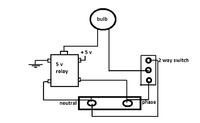
 

This is not safe! This is not how 3-way switches are used in domestic circuits. In your drawing, the 3-way switch has 220V across it (i.e. the two end contacts), and so has your relay! In domestic circuits, the switch is only in the path of the live connection (phase), not the neutral connection (look at the bottom of this link: **broken link removed** ).
I wouldn't experiment any further with your circuit if I were you.
If you want a safe way, get a solid state relay and don't try this changeover mechanism. Instead, just have the IR output, and a low voltage switch to control the relay (i.e. use low voltage for the switch too). It is a simple XOR gate.
 
  • Like
Reactions: rahib

    rahib

    Points: 2
    Helpful Answer Positive Rating
Try this way:


The snubber diodes = two inverse-series 5V6 zener diodes
 

Attachments

  • Relay_SPDT switch.jpg
    Relay_SPDT switch.jpg
    254.1 KB · Views: 220

This is not safe! This is not how 3-way switches are used in domestic circuits. In your drawing, the 3-way switch has 220V across it (i.e. the two end contacts), and so has your relay! In domestic circuits, the switch is only in the path of the live connection (phase), not the neutral connection (look at the bottom of this link: **broken link removed** ).
I wouldn't experiment any further with your circuit if I were you.
If you want a safe way, get a solid state relay and don't try this changeover mechanism. Instead, just have the IR output, and a low voltage switch to control the relay (i.e. use low voltage for the switch too). It is a simple XOR gate.

thank you for your suggestion.I have tried your approach its easy and working
 

Friends I have made a IR controlled witch and now I want to couple it with the 2 way switch (as used in domestic electric boards) so that i can operate my device with IR remote as well as with the switch.Its just like using two 2 way switch just one of the 2 way switch is replaced by the relay.But here i am facing the problem
the traditional diode cannot be used because coil current needs to flow in both directions and whenever i switch the polarity through relay circuit breakdown occurs.sometimes it work fine but 1 out of 4 times breakdown occurs.I can see some electric arcs in relay
the relay i am using is 5V/220V.Please help me.

basic schematic of relay with 2 way switch

[url=https://obrazki.elektroda.pl/60_1330872866.jpg][/URL]


Hi, my friend you didnt tell us what current that 5V relay switch, what load you put on it.


You say :

But here i am facing the problem
the traditional diode cannot be used because coil current needs to flow in both directions and whenever i switch the polarity through relay circuit breakdown occurs.

How you mean that ? You can use diode for relay coil to prevent spikes. You didnt put 220V on relay coil ? :shock:
Through relay coil should pass DC current in one direction, not AC 220V!!!!! :shock:

I think you have bad design, and setting of problem.


Switch should be used only to swtich relay coil, and relay contacts switch 220V load.

Relays have two state of output contactor, Normally Open NO, and Normaly Conected NC, you should use each for needed state.
 
Last edited:

Status
Not open for further replies.

Similar threads

Part and Inventory Search

Welcome to EDABoard.com

Sponsor

Back
Top