Continue to Site

Welcome to EDAboard.com

Welcome to our site! EDAboard.com is an international Electronics Discussion Forum focused on EDA software, circuits, schematics, books, theory, papers, asic, pld, 8051, DSP, Network, RF, Analog Design, PCB, Service Manuals... and a whole lot more! To participate you need to register. Registration is free. Click here to register now.

[SOLVED] Relay or MOSFET for 24V and 2A

Status
Not open for further replies.

onklen

Newbie level 3
Joined
May 12, 2016
Messages
4
Helped
0
Reputation
0
Reaction score
0
Trophy points
1
Activity points
35
I'm working on a small project where I want to use my Raspberry PI to turn on/off a power resistor for temperature control. I'm looking at a maximum of 50W and I have a 24VDC power supply so I will be looking at approximately 2A through the power resistor.
Would this design be best by using a MOSFET to activate a 24VDC relay or would it be fine to simply use a MOSFET that would be rated for 2A and skip out on the relay?
I'm hoping that I can drive it directly from the Raspberry PI so naturally the gate current would need to be kept low as well as the gate voltage as I won't have more than 5V.
Any good advices on a specific MOSFET that might be handy?

Regards,
Rolf
 

Hi,

A simple N MOSFET will do.
there are thousands.

Look for:
* VDS > 30V (better 40V)
* V_GS_TH < 3V
* R_DS_ON < 50mOhms (At 4.5V V_GS or below)

About all manufacturers have intractive selction guides.
Also distributors like farnell, digikey, mouser...

Select the package you like..

Klaus
 
  • Like
Reactions: onklen

    onklen

    Points: 2
    Helpful Answer Positive Rating
If you planned to supply the relay coil with the same voltage already used by logic devices, I agree to prefer an N-Mosfet. Relays in general generate expressive spike on power bus during On/Off switching.
 

Thanks a lot for the answers.
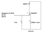
I've found a MOSFET and I've tried to put together a simple schematic. Does the MOSFET and schematic make sense?
Any help is most appreciated.
**broken link removed**
schemeit-project.png
 

Hi,

don´t connect the load in the SOURCE wire of the mosfet, but connect in in the DRAIN wire.

Klaus
 
  • Like
Reactions: onklen

    onklen

    Points: 2
    Helpful Answer Positive Rating
Thanks a lot for the answers.
I've found a MOSFET and I've tried to put together a simple schematic. Does the MOSFET and schematic make sense?
Any help is most appreciated.
**broken link removed**
View attachment 128993

For the resistive load try PVG612, a power opto coupler. Input is a LED drive, TTL, some 5 mA, isolated MOSFET can switch 60 V, 2 A. I tested several devices at up to +125 deg.C, failure undr 2 A load occurred at 130 deg.
 

With a 5V input then the output of your N-channel Mosfet will be 1V to about 2.5V because it is a "source-follower". Its gate must be 1.5V to 4.5V (b) higher(/b) than its source for it to turn on.
 
  • Like
Reactions: onklen

    onklen

    Points: 2
    Helpful Answer Positive Rating
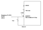
I've had another look at it and found another MOSFET and moved the load.
With this MOSFET (**broken link removed**) is seems to be having Rds 0.03Ω. So with the 10Ω resistor there will be 0.06V over the MOSFET? Is that even close to being correct?
If that's true then 5V should be more than enough to fully turn on the MOSFET?
schemeit-project (1).png
 

Hi,

everything is correct.

:)


Klaus
 
  • Like
Reactions: onklen

    onklen

    Points: 2
    Helpful Answer Positive Rating
That's excellent. Thanks for all the help.
 

Status
Not open for further replies.

Part and Inventory Search

Welcome to EDABoard.com

Sponsor

Back
Top