Continue to Site

Welcome to EDAboard.com

Welcome to our site! EDAboard.com is an international Electronics Discussion Forum focused on EDA software, circuits, schematics, books, theory, papers, asic, pld, 8051, DSP, Network, RF, Analog Design, PCB, Service Manuals... and a whole lot more! To participate you need to register. Registration is free. Click here to register now.

relay driving using bc547

Status
Not open for further replies.

micro_man

Newbie level 6
Joined
Dec 9, 2013
Messages
13
Helped
0
Reputation
0
Reaction score
0
Trophy points
1
Activity points
106
hi
its a basic question, but i want to know if i am doing write calculations or not
i want to drive a relay using bc547 transistor, relay has a coil resistance of 320 ohms, driving voltage is 12v. so the current required is 37.5mA.
after calculating all the others parameters i get the value of Rb=6.323kohms. Is it write? and is the transistor is in saturation region?
IMG_20150812_235655.jpg
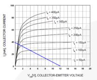
Also tell me how to read the graphs of the transistors and how to get help form these graphs?
Capture.PNG
thanks
 
Last edited by a moderator:

The current gain of the transistor series BC546/7/8 is defined by the suffix -A -B or -C.
In the worst case, you migh use the smaller gain to ensure saturation of the transistor.

See that: https://en.wikipedia.org/wiki/Bc547
 
In the case of ensuring the transistor is fully saturated, I suggest you aim for higher base current. The calculation is correct for linear operation, in this case doubling the base current may not be enough to ensure saturation, even with a high gain band transistor. I would suggest at least 5 times and maybe as much as 10 times the base current is used.

Brian.
 
You did not read the datasheet so you were guessing that the base current should be double the current calculated from the minimum current gain. The current gain is listed when the transistor is linear with 5V Vce, not saturated. Your guess was close. The datasheet for most small European transistors like the BC547 shows in writing the typical and maximum saturation voltage when the base current is 1/20th the collector current without mentioning its current gain. Small American transistors like a 2N3904 have their maximum saturation voltage listed when the base current is 1/10th the collector current even though some of them have a current gain of 300.

The graphs show only "typical" transistors that you cannot buy, many are sold with less than typical spec's. You do not want to buy thousands of a transistor and test them all so that you can pick only the "typical" or better ones, if there are any.
 
Thanks everyone.
I am still confused. What should i do? always multiply the base current with 5 or 10 for the safe side to saturate the transistor? or do something else to ensure the correct operation. What should be the Vce for operation in saturation region?
What 1st graph shows?
i am confused in transistor portion.
 

What 1st graph shows?
It's the transistor output characteristic. You can add a relay load line to the diagram and read Vce for different base currents, valid for typical transistor parameters, as said. Because you want Vce to be small, there's nothing against making Ib larger. You'll notice that Vce,sat is specified in datasheets for a "forced B" of e.g. 20. I won't go above 50, means 1 mA base current is a very comfortable value.


The bottom line is: there is no harm done in using more base current than necessary. Biasing in the linear region is not good, the relay may not operate and the transistor will probably warm up. As you increase the base current the collector voltage will drop and there is more current available for the relay (= good) but each transistor will be slightly different so it's safer to err on the side of caution and allow more base current than the theoretical minimum needed. Increasing the bias current beyond the transistor saturation point (within sensible limits!) doesn't make much difference to the collector current but buys you the security that the relay is fully powered..

Brian.
 

Thanks everyone.
I am still confused. What should i do? always multiply the base current with 5 or 10 for the safe side to saturate the transistor? or do something else to ensure the correct operation. What should be the Vce for operation in saturation region?
What 1st graph shows?
i am confused in transistor portion.
DO NOT use the current gain (hFE) to determine the base current for a saturated transistor because the current gain is used only when the transistor is a linear amplifier with plenty of Vce (5V for the BC547).
DO NOT use the graphs that are only for "typical" transistors because the ones you buy might have minimum or maximum spec's.
The datasheet has the printed maximum saturation voltage (Vce) when the base current is 1/20th or 1/10th the collector current and this spec is guaranteed for EVERY transistor with that part number.
 

Status
Not open for further replies.

Similar threads

Part and Inventory Search

Welcome to EDABoard.com

Sponsor

Back
Top