wandola
Junior Member level 3

- Joined
- Jul 20, 2005
- Messages
- 31
- Helped
- 0
- Reputation
- 0
- Reaction score
- 0
- Trophy points
- 1,286
- Activity points
- 1,554
Dear All,
I am designing a conventional relaxation oscillator. The moninal frequency is around 2.85 MHz.
When I try to run the transient noise simulation and use calculator to obtain the eye diagram, I got some weird diagram and i am very much confused.
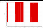
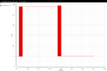
Attached you can see some waveforms obtained using the function eye diagram. The setting is pretty simple. Just set the start and stop time. The period is the oscillator output frequency period. I just took an average value for this. The weird thing is that when I changed the period by a little bit, the plotted diagram is very different.
Can some expert help me with this? I don't know how i should proceed.
For the first graph, the period is 351.5 ns; for the second one, the period is 351.3 ns; the last one has period of 351.25 ns.
Please help me with this. thanks a lot guys.
Attachments
Last edited by a moderator:


