Continue to Site

Welcome to EDAboard.com

Welcome to our site! EDAboard.com is an international Electronics Discussion Forum focused on EDA software, circuits, schematics, books, theory, papers, asic, pld, 8051, DSP, Network, RF, Analog Design, PCB, Service Manuals... and a whole lot more! To participate you need to register. Registration is free. Click here to register now.

Rejection of BPF filter in EM simulation

Status
Not open for further replies.

shyamss

Newbie level 3
Joined
Nov 29, 2011
Messages
4
Helped
0
Reputation
0
Reaction score
0
Trophy points
1,281
Activity points
1,316
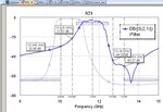
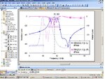
i'm designing a Microstrip narrowband BPF at center frequency 11.65GHz on substrate RT Duroid-6010LM having εr=10.2 using AWR Microwave office.. i've selected the Hairpin design methodology for my design. and i found my order of the filter as 7th order. i want rejection of 65dB at 10.05GHz and 13.25GHz, this was achieved in the schematic design in the tool. for any higher frequency design we've to go for the EM simulation, so i did the EM simulation using AXIEM simulator. But where i'm losing the Rejection at the given band to the half (ie., 30db or so) at both side of the skirt. So i've increased the order to 8 even though i've increased the Rejection to 40dB not more than that. and even i've given with the Constrains of length×width×height so if i further increase my order to achieve Rejection i'll be violating the constrains. So what do i want to do to increase the rejection at the skirts with the 7th or the 8th order.. Someone plz help with this regard.
 

This could be coupling from the input to the output, which is included in the EM model.
The schematic is ideal there, because it has no such parasitic coupling effects.
Depending on your layout, you could try to increase the distance/isolation between
input and output, or possibly use some shielding.
 

i'm designing a Microstrip narrowband BPF at center frequency 11.65GHz on substrate RT Duroid-6010LM having εr=10.2 using AWR Microwave office.. i've selected the Hairpin design methodology for my design. and i found my order of the filter as 7th order. i want rejection of 65dB at 10.05GHz and 13.25GHz, this was achieved in the schematic design in the tool. for any higher frequency design we've to go for the EM simulation, so i did the EM simulation using AXIEM simulator. But where i'm losing the Rejection at the given band to the half (ie., 30db or so) at both side of the skirt. So i've increased the order to 8 even though i've increased the Rejection to 40dB not more than that. and even i've given with the Constrains of length×width×height so if i further increase my order to achieve Rejection i'll be violating the constrains. So what do i want to do to increase the rejection at the skirts with the 7th or the 8th order.. Someone plz help with this regard.

As volker_muehlhaus points out, this could be coupling directly from input to output.

It might be instrumental at this point to simply perform a test in the AXIEM EM simulator where the input and the output (both ports) are simply terminated in 50 Ohms. Make the 'runs' on the substrate to the same closest physical points that connect to your filter and instead place 50 Ohm terminations (resistors) right at those places.

This will give you some idea what the 'practical' intrinsic limits are given your layout and determine what you can achieve as to ultimate input/output isolation. Better to have a 10 dB or better margin as well, so, if you need 65 dB filter rejection your input/output layout 'margin' would indicate a desired 75 dB figure or better. That is a power ratio of almost 40 million:1 (76 dB would be a 40million:1 power ratio if my math ratio is correct). This is usually where shielded 3D 'cavity' structures (milled aluminum etc) are used rather than 2D planar structures on a substrate where some level of fields can couple from input to output.

RF_Jim
 

thank u for ur hands, but can brief for me about the shielding.. and other thing is "increase in spacing itself will improve my rejection". i've increased my order from 7 to 8. so only the spacing will do my stuff or i've to and any other external components to my design.. and give some info about the shielding u said..
 

If the problem is crosstalk, it does not help to increase the order. Your schematic level simulation has shown that the order is high enough.

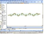
Can you show the layout and response that you get?
 

It is the coupling between the input and output ports as your circuit is quite small at that frequency.
 

IL & RL.JPGLayout.JPGS21.JPG

Please look into the results and comment on them. The order of the filter is 8.
 

For these wide lines, the circuit models are not accurate. I think this is the main reason why the initial circuit simulation results are much different from the EM result. They are different in everything, not just rejection.

Without having accurate circuit models, you will need time consuming EM based optimization, or some hybrid method that combines EM and circuit models.
 

i've used same circuit models which are used in Nuhertz model as said in your link. ie., MXCLIN, and the 180 deg bend.. even though i'm finding the difference. for the lesser frequency using the same circuit models we'll not find this much of difference but for my frequency (ie., 11.65GHz) i'm getting lot of difference..
 

i've used same circuit models which are used in Nuhertz model as said in your link. ie., MXCLIN, and the 180 deg bend..

I've worked with Nuhertz a while ago, and the new method they suggest is to start with circuit models, but then switch to full EM with some additional ports for fine tuning. From my experience, the circuit models are not accurate enough for example at the T-junction. With your very wide lines, that is even more critical and I would expect the circuit model to be off quite a bit.

One more throught: the lines are very wide, compared to the resonator length. This introduces an additional challenge for the accuracy of the circuit models, and also requires those wide gaps. Could you switch to a thinner substrate, for smaller line and gap width? I would expect that circuit models would be more accurate then.
 

Status
Not open for further replies.

Part and Inventory Search

Welcome to EDABoard.com

Sponsor

Back
Top