Continue to Site

Welcome to EDAboard.com

Welcome to our site! EDAboard.com is an international Electronics Discussion Forum focused on EDA software, circuits, schematics, books, theory, papers, asic, pld, 8051, DSP, Network, RF, Analog Design, PCB, Service Manuals... and a whole lot more! To participate you need to register. Registration is free. Click here to register now.

Regulated power supply ground?

Status
Not open for further replies.

hmalissa

Junior Member level 2
Joined
Apr 21, 2010
Messages
23
Helped
0
Reputation
0
Reaction score
0
Trophy points
1,281
Location
New Jersey
Visit site
Activity points
1,492
I need a regulated voltage supply with +/-15V output in order to power an instrumentation amplifier circuit. The purpose of this circuit is to avoid a ground loop, so ground needs to be referenced by the application only and not by the power supply.
I am thinking about using a solution with a 7815 and a 7915 regulator, similar to the one shown in figure 6 in https://www.ti.com/lit/ds/symlink/ua7815.pdf. I am wondering if this will do and what kind of voltage supply I need for the +/-20V input. Are batteries the only option? And is the circuit in figure 6 the most suitable solution?
 

what kind of voltage supply I need for the +/-20V input. Are batteries the only option? And is the circuit in figure 6 the most suitable solution?
For the +/- 20 V you can use batteries.
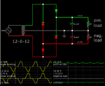
But you could use the mains supply for +/- 20 V as i did.Attached is a schematic of a power supply i did,just add those diodes,i think you should be good.
Before the 7815 i am getting 24 V in my schematic unlike 20 V in your case,but i don't think it should be an issue.

I attached a second schematic(slightly different)on how to obtain a bipolar supply from center tapped transformer.
It only needs 4 diodes. No short-circuits occur.
The website below discusses the problem of the initial bipolar supply.
https://mysite.du.edu/~etuttle/electron/elect9.htm
Image from website (scroll down about 90%).
 

Attachments

  • Capture.JPG
    Capture.JPG
    166.4 KB · Views: 98
  • 7068130100_1369362863.png
    7068130100_1369362863.png
    21 KB · Views: 97
  • 9914318300_1369363251.png
    9914318300_1369363251.png
    5.2 KB · Views: 94
Last edited:
That was very helpful, thanks a lot.
So if I get two simple unregulated 20V or 24V AC/DC converters ('wall-warts', for example) and tie the positive output of one to the negative output of the other, and use those as the input voltages of the regulator circuit, will that give me a ground that's not referenced to anything but my application?
Yes, that will work. You may also be able to buy 15Vdc output wall-warts with the regulators built-in.
 
If you are thinking of buying 24V adapter & then 7815 & 7915 chips,why don't you directly buy regulated 15 V adapter.

  • You can also do your job with a single 24 V adapter,and use a isolated DC-DC Brick(i think they may be costly) or an inverting buck-boost converter.
  • If you are going to design your own circuit with 7815 & 7915,i think buying a centre-tapped transformer & 2 bridge-rectifier as in that schematic might be cheapest.

Just see which method is better for you
 

why don't you directly buy regulated 15 V adapter.

You mean SMPS? Probably because you'd introduce a unholy amount of ripple and because of the total lack of accuracy, especially under light load conditions...
 

No,was taking about a wall-wart with regulators built within them.

The modern regulated power adapter's do have a high efficiency and tighter regulation control.
Many modern regulated switching power adapters offer multiple user selectable DC output voltages, (all regulated) and come with a range of user configurable output connectors. The user may select from a range of available output connector types and sizes, and change the output polarity of the connector as well.
 
Last edited:

Status
Not open for further replies.

Similar threads

Part and Inventory Search

Welcome to EDABoard.com

Sponsor

Back
Top